3.2.5. Associations
450 likes | 593 Vues
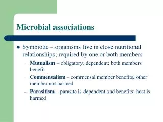
3.2.5. Associations. The relations is_a and has_a are fundamental ways to understand collections of classes. In an OO implementation these relations will usually be visible in the code. But they are not the only interesting relations!. Almost every OO model features relations

3.2.5. Associations
E N D
Presentation Transcript
3.2.5. Associations The relations is_a and has_a are fundamental ways to understand collections of classes. In an OO implementation these relations will usually be visible in the code. But they are not the only interesting relations!
Almost every OO model features relations which are ad hoc and reflect the special semantical meaning or intension of classes. Such general relations are called associations. They are used in database theory, where • records, and • relationships between records are described in Entity/Relationship diagrams.
Reasons: • because two or more objects may exchange messages or services, • because two or more objects may co-exist independently, or dependently • because a relation may clarify the meaning of a class when we don’t quite know what it is yet. • etc. etc. …
So aspects of dynamical behaviour and meaning may be visible in a (static) class diagram. An important association will be reflected in the code somewhere, but not in any naïve way, e.g. inheritance construct, line 27, etc.
The simplest association is binary and represented by a line … e.g. <name> Class_A Class_B Normally, we at least annotate the association with a <name>, e.g.
studies Student Course name title An arrow can be added to show the orientation or asymmetry of the relation. In this case studies is not symmetric.
Actually, this asymmetry is already implicit in the two different class names. We can also make the asymmetry explicit and more interesting by assigning role names For example …
subject Student Course participant name title The existence of an association between two classes often indicates some level of coupling, in the sense of related concepts. According to standard practice, coupling should be minimized and cohesion maximized.
Excessive coupling often indicates a bad architectural decomposition. Many associations (relations) are binary, but not all! Some are: • ternary relations (3 arguments) • n-ary relations (n arguments)
Men Women E.g. a ternary relation can be drawn as: marries Priests and we can add more classes to the diamond.
3.2.6. Multiplicity of Associations In an ER diagram it is common to give the multiplicity of each component of a relation. In OO analysis and design this can help to implement, test and debug the code.
The commonest multiplicities are: • One-to-one tax_coding John Smith 760901-1234 Mary Jones 691205-5678 People Tax_codes
mother_of • One-to-many M.E. Meinke K. Meinke N. Meinke Women People
parent_of • Many-to-many M.E. Meinke K. Meinke K.W. Meinke N. Meinke People People
Relation R between classes X and Y is: n-to-… if for every object y :Y there are n distinct objects x1 ,…, xn : X with xiR y for i = 1 ,…, n …-to-m if for every object x :X there are m distinct objects y1 ,…, ym : Y with x R yi for i = 1 ,…, m
So e.g. parent_of is 2-to-many. UML has a notation for multiplicity: • 1 one and only one • 0 .. 1 zero or one • M .. N from M to N • * greater than or equal to zero • 0 .. * …same … • M .. * greater than or equal to M
1 1 Class_A Class_B Examples: one-to-one one-to-many 1 * Class_A Class_B
many-to-many * * Class_A Class_B We can also add multiplicity constraints to aggregation and composition relations, e.g. …
1 Class_A object has many Class_B objects 1 * Class_A Class_B
We can express a choice of multiplicities in other ways, e.g • 1, 3, 5 1 or 3 or 5 • 7, 9 .. 12 7 or 9 or 10 or 11 or 12
package MyPackage abstract class MyAbstractClass package MyPackage class MyDerivedClass extends MyAbstractClass { int att; void myFunction( referencedClass r ) { .. } } 3.3. Mapping to Code MyPackage MyAbstractClass MyDerivedClass att: int myFunction()
class MyClass { MyAggregatedClass ac; int att; void myFunction( referencedClass r ) { .. } } Aggregation MyClass att: int myFunction() ac MyAggregatedClass
class MyDependentClass { void myFunction1( MyReferencedClass r ) { .. } MyreferencedClass myFunction2( .. ) { .. } void myFunction3( .. ) { MyReferencedClass m .. } } Dependence 3 possible implementations! MyClass att: int myFunction() dependence arrow MyReferencedClass
3.3. Object Diagrams Introduction. An object diagram represents a specific collection of objects, with specific attribute values and relationships. Therefore it looks like a snapshot of an O-O system at some instant in time.
We can draw an object diagram to try to instantiate a particular class diagram. An object diagram O is a valid instance a class diagram C if, and only if, O satisfies all the constraints (numerical and logical) of C. This means we must check (validate) whether O really instantiates C.
In fact, even without any class diagrams, we can just draw object diagrams to help us think about how the system might look. So object diagrams are a complement or an alternative to class diagrams. An object diagram is also called an instance diagram.
Common uses of object diagrams are: • to illustrate the system state at a high level of abstraction, before and after some action (e.g. instruction execution) i.e. dynamic modeling !! • to analyze the structure of recursive data types (classes) by unfolding a class diagram.
3.3.1. Objects An object is drawn as a rectangle, containing possibly the: • object name, • object type (class), • attribute names, • attribute values. For example …
typeless name name : type name : type : type attribute = value anonymous
3.3.2. Links A link is a concrete instance of an association or relation. A class can be modeled as the set of all its instances. Then an n-ary association (relation) R is modeled as an n-ary relation on these sets.
In this case, a link is a specific n-tuple of objects: l = ( o1 , …, on ) R Graphically a link looks like an association, only the context distinguishes the two. Association and role names are copied over to links.
However: • Logical constraints on associations are carried over as the presence or absence of links. 2. Numerical constraints on associations are carried over as numbers of links between endpoints.
has For example, the following object diagram (below) is a legal instance of the class diagram (above): Biplane Wing 2 Upper_wing : Wing has Sopwith-Camel : Biplane has Lower_wing : Wing
But this object diagram is not a valid instance of the previous class diagram: Sopwith-Camel : Biplane Lower_wing : Wing has since it has the wrong number of links (1 instead of 2 on RHS)
Ternary and n-ary relations are represented using the diamond as before, e.g. Object_1 : Class_1 Object_2 : Class_2 Object_3 : Class_3
Object composition and aggregation use the same symbols as for classes, e.g. Component1 : Class_1 Component2 : Class_2 Object : Class
Notice that now we can capture the semantic difference between composition and aggregation. E.g. the following is illegal P1 : Polygon L1 : Line !!!!! Start : Point Myname : Name text = “big” x = 0 y = 0
We can use object diagrams to understand recursively defined classes. For example, the class diagram Binary_Tree 0,1 0 .. 2
T1 : Binary Tree has the object diagram T2 : Binary Tree T3 : Binary Tree T4 : Binary Tree T5 : Binary Tree
4. Software Architectures Software architecture: structure or structures of the system which comprise software components, externally visible properties of these components, and relationships among them. Not the operational software!
Purposes: enables software engineer to … • Analyse effectiveness of design in meeting requirements .. • Because small intellectually graspable model of how components collaborate • So, consider architectural alternatives at a stage when making changes is still easy • Hence, reduces project risks associate with software construction.
Lets see a classification of architectures, taken from M. Shaw & D. Garlan, Software Architecture, Prentice Hall, 1996. Note: our list is just a sample!
4.1 Data Flow Data flows between static functional elements which transform it, aka pipeline architecture e.g. compiler C code assembler Machine code parse tree Parse Translate Link & Assemble procedure calls assembler Library
4.2. Model-View-Controller MVC • An architectural model that solves many user interface (UI) problems, e.g. • shared data, • multiple users, • different views of the same data, • updating information across all users, • changes to underlying data, • changes to representation
Architecture Goals • Same information capable of being presented in different formats in different windows • Changes made in one view should be immediately reflected in other views • Changes in the UI should be easy to make • Core functionality should be independent of the interface to enable multiple interface styles