5. Application Examples
5. Application Examples. 5.1. Programmable compensation for analog circuits (Optimal tuning) 5.2. Programmable delays in high-speed digital circuits (Clock skew compensation) 5.3. Automated discovery – Invention by Genetic Programming (Creative Design) 5.4. EDA Tools, analog circuit design

5. Application Examples
E N D
Presentation Transcript
5. Application Examples 5.1. Programmable compensation for analog circuits (Optimal tuning) 5.2. Programmable delays in high-speed digital circuits (Clock skew compensation) 5.3. Automated discovery – Invention by Genetic Programming (Creative Design) 5.4. EDA Tools, analog circuit design 5.5. Adaptation to extreme temperature electronics (Survivability by EHW) 5.6. Fault-tolerance and fault-recovery 5.7. Evolvable antennas (In-field adaptation to changing environment) 5.8. Adaptive filters (Function change as result of mission change) 5.9 Evolution of controllers 1
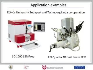
Genetic design of antennas – Linden’s crooked wire antennas Fig. 1 Possible novel designs, e.g. tree like antennas [LIN97] • A Genetic Algorithm was used in conjunction with the Numerical Electromagnetic Code, Version (NEC) (as simulator) to create and optimize atypical wire antenna designs with impressive characteristics [LIN97]. Evolutionary techniques may revolutionize the design of wire antennas. • GA-optimized Yagi antennas surpass by ~1dB the gain of conventional Yagis • Crooked-wire antennas, consisting of wires joined at various locations and with various lengths (both determined by GA), evolved to unusual shapes, unrealizable using conventional design, and demonstrated excellent performance both in simulations and physical implementation • Other ideas about evolvable antennas • Use real reconfigurable antenna, morphing in real time under evolutionary control • Components of reconfigurable antennas could be macroscopic (e.g., actuated wires) or MEMS • Evolution of antenna arrays • Co-evolution of antenna & electronic interface (e.g., for matching impedance, etc.) 2
ST5 Antenna Requirements • Transmit Frequency: 8470 MHz • Receive Frequency: 7209.125 MHz • Antenna RF Input: 1.5W = 1.76 dBW = 31.76 dBm • VSWR: < 1.2 : 1 at the antenna input port at Transmit Freq, < 1.5 : 1 at the antenna input port at Receive Freq • Antenna Gain Pattern: Shall be 0 dBic or greater for angles 40 <= theta <=80; 0 <= phi <= 360 • Antenna pattern gain (this shall be obtained with the antenna mounted on the ST5 mock-up) shall be 0.0 dBic (relative to anisotropic circularly polarized reference) for angles 40 <= theta <=80; 0 <= phi <= 360, where theta and phi are the standard spherical coordinate angles as defined in the IEEE Standard Test Procedures for Antennas, with theta=0 to direction perpendicular to the spacecraft top deck. The antenna gain shall be measured in reference to a right hand circular polarized sense (TBR). • Desired: 0 dBic for theta = 40, 2 dBic for theta = 80, 4 dBic for theta = 90, for 0 <= phi <= 360 • Antenna Input Impedance: 50 ohms at the antenna input port • Magnetic dipole moment: < 60 mA-cm^2 • Grounding: Cable shields of all coaxial inputs and outputs shall be returned to RF ground at the transponder system chasis. The cases of all comm units will be electrically isolated from the mounting surface to prohibit current flow to the spacecraft baseplate. • Antenna Size: diameter: < 15.24 cm (6 inches), height: < 15.24 cm (6 inches) • Antenna Mass: < 165 g 3
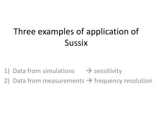
Antenna Genotype f rx f f rx rz • Genetic representation is a small programming language with 3 instructions • place wire • place support • branch • Genotype specifies design of 1 arm in 3-space • Genotype is tree-structured computer program that builds a wire form • Commands: • forward(length radius) • rotate_x(angle) • rotate_y(angle) • rotate_z(angle) • Branching in genotype • branching in wire form Work by Lohn and Linden 4
Fitness Function VSWR Work by Lohn and Linden 03 • Antenna designs are evaluated by NEC4 running on Linux Beowulf supercomputer • 3 copies w/added noise are evaluated for each design • Fitness function (to be minimized):F = VSWR_Score * Gain_Score * Penalty_Score • VSWRs from both freqs arescaled and multipliedGain is sampled at 5 degree increments between theta=40 and theta=90 f = 0 if gain > 0.5 dB f = 0.5 – gain if gain < 0.5 dB • Penalty: proportional to # gain samples less than 0.01 dB VSWR stands for Voltage Standing Wave Ratio The antenna is usually located some difference from the transmitter and requires a feedline to transfer power between the two. If the feedline has no loss, and matches BOTH the transmitter output impedance AND the antenna input impedance, then - and only - then will maximum power be delivered to the antenna. In this case the VSWR will be 1:1 and the voltage and current will be constant over the whole length of the feedline. Any deviation from this situation will cause a "standing wave“ of voltage and current to exist on the line. 5
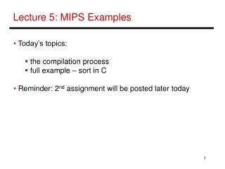
Evolvable antenna system • Goal: to explore the in-situ optimization of a reconfigurable antenna (vs. optimization on a controlled antenna range) • Software evolves relay configurations, user subjectively ranks designs based on signal quality (future work will automate this process) • 30-relay antenna created, along with all necessary software to control and evolve it • System is able to optimize effectively for frequencies in the upper portion of the VHF broadcast TV band (177 - 213 MHz) • 1.5m diagonal length (about 1 wavelength at above frequencies) • Continuing work: improve optimization effectiveness, expand number of relays and antenna size to enhance low frequency performance Relay module • Evolvable antenna concept developed by Linden & Stoica • Antenna work performed by D. Linden. JPL funding 1999-2001 30-relay antenna 6
Evolvable antenna system Motivation: adapt to changes in spacecraft configuration and orientation as well as damage • Demonstrated • Automatic evolution of reconfigurable antennas • Antenna adaptation to different barriers, orientations, frequencies, and loss of control • Superior performance over conventional antenna Antenna 1999-2000 Barrier 10 750 cm RF Generator 0.4 30cm RF cable RF Receiver PC Audio cable Control cables USB cable DAQPad 6507 Evolvable antenna concept by Linden & Stoica Work by Dr. Linden of LIR with JPL funding 7
Evolvable Antenna Incoming & Outgoing Signals Computer receiving / transmitting data RF Transceiver Reconfigurable Antenna RF Signals Digital Signals Rec’d Signal Strength Indicator (RSSI) Voltage Control Signals A/D converter Digitized RSSI Voltage Genetic Information Antenna Control Interface Evolutionary Optimization Software Work by Derek Linden with JPL funding dlinden@lindenir.com Objective: show that an evolved reconfigurable antenna, in-situ adapted to environment, can outperform conventional antennas. Frequency: 2.4 GHz. Transceiver sends and receives IP data, can send data while EvAn is being optimized, provides a Received Signal Strength Indicator (RSSI) voltage output 2000-2001 8
Physical Setup Antenna Barrier (Al sheet, 40 cm x 46.4 cm x 0.5 mm) Dipole Antenna 30 375 cm 1.0 12.5 cm RF Transceiver RF cable RF Transceiver Data cable Wire (RSSI Voltage) PC A/D Conv RSSI Data cable USB cable DAQPad 6507 Control cables 9
Reconfigurable Grid Antenna • Reconfigurable grid antenna • 48 Reed relay switches • 13.2 cm x 10.5 cm overall size • 2.1 cm cell size • SMA coaxial cable connection for RF signal • Coaxial control lines feeds control coils • Control lines are roughly perpendicular to plane of antenna to limit interference • Tuned 5/8 wave antenna used as baseline • 50 ohm input impedance • 3.0 dBi nominal gain at the horizon • ~23 cm in length • Omnidirectional in azimuth 10
DEvAn System Details • A/D Converter • Changes analog RSSI voltage from transceiver into 8-bit digital signal into NI DAQPad • LEDs indicate status of digital outputs and read/hold input • Ribbon cables connect to DAQPad, wires connect to switches • Range 0 – 5 v used, transceiver uses 1.4 – 4.5 v for RSSI Antenna control interface • National Instruments DAQPad 6507 • Connects to USB port on PC • Directly drives antenna switches (48) with TTL output • Receives digital RSSI input (8 bits) • Photo shows DAQPad open, displaying its screw terminals • Software drivers convert genetic code into the command strings • Same unit as for previous EvAn project • DEvAn uses ribbon cable for controls and input connected to ADC unit • Transceiver • Aerocomm PKLR2400S 2.4 GHz transceiver • 10 mW • OEM Developer version • Serial comm port on board • Wires are for ground and RSSI voltage to ADC 11
Chromosome Mapping • Binary chromosome used • The 1s and 0s in the chromosome correspond to closed and open switches (1 closed, 0 open) • The connections between the DAQPad and the switches define the chromosome mapping • Wire connections are essentially fixed in place • Mapping is done in software • Used spiraling to helpcorrespond physical distance with distance on chromosome 12
Objective function and GA Parameters • GA Parameters • Fitness-proportional selection with scaling • One-point crossover • All individuals evaluated in each generation • Top 50% carried to next generation • Mutation rate = 20% • Population size = 10 • 10 generation limit (+ initial generation) • Objective Function Maximize RSSI level • Uses digitized voltage • Favors designs with increased values • Very noisy, bi-modal signal • Overcome with repeated testing, averaging, rejection regions 13
Evolution and Test Matrix Objective: Evolve to maximize RSSI level Hypothesis: Higher signal input => better data transmission 3 Orientations • Broadside (plane of antenna |_ to signal) • 45 deg • Endfire (plane of antenna // to signal) 2 Barrier configurations (placed before optimization begins) • None • Solid metal (Al) sheet Polarization is vertical for all tests 14
Results Score: higher is better Stdev: lower is better Without Barrier With Barrier 15
Adaptation to Environment Perfect conducting wire mesh 40 cm x 46.4 cm, 12.5 cm above antenna, with 2 cm x 2 cm cells (Aluminum sheet was used in the hardware test) Showing optimal configuration found in hardware 5/8-wave Antenna Optimized Antenna Antenna adaptation to different barriers and orientations, outperforms conventional commercial antenna. 16
Scores vs dB gain • A rough calibration exists for voltage (score) vs dBm • For baseline vs DEvAn broadside: • Baseline score: 119.0 score => -59.1 dBm • DEvAn score: 129.5 score => -56.4 dBm • Difference: 2.7 dBm • This indicates that almost twice as much power was delivered by DEvAn than by the baseline antenna 17
General Observations • Time to optimize • ~8 minutes per 10-generation run • Antenna reconfigured in <0.1 seconds • Time mostly due to re-sampling RSSI voltage • Repeat runs of the same antenna and test configuration gave very similar performance • Noise was a major challenge, as it was in the original EvAn system 18
Relationship Btw RSS and Data Transmission • Hypothesis: Higher signal input => better data transmission • Testing done with packet-level data communications program with test data sent over network • Having fewer errors translates into having greater bandwidth • Tests performed with packet-level send and receive program • Script used to continuously transmit packets across the network • Number of errors per 2400 packets recorded (repeated 5 times) • Separation: 16.5 There appears to be a “sweet spot” for RSSI. Highest is notnecessarily the best for data transmission! Needs further exploration. 19
Conclusion Accomplishments • Testing of 2.4 GHz reconfigurable antenna that can both receive and transmit • Automatic evolution of reconfigurable antenna using RSSI while leaving data channel usable • Antenna adaptation to different barriers and orientations • Performance above that of a conventional commercial antenna 20