Download
1 / 30
300 likes | 840 Vues
5. Combinational Circuits. Objectives : To recognize the principal types of combinational circuits Adders and subtracters Decoders, comparators, converters Multiplexers and demultiplexers Logical programmable: ROM, PAL, PLA Arithmetic logic unit (ALU)

E N D
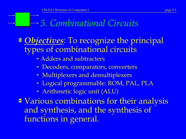
5. Combinational Circuits • Objectives: To recognize the principal types of combinational circuits • Adders and subtracters • Decoders, comparators, converters • Multiplexers and demultiplexers • Logical programmable: ROM, PAL, PLA • Arithmetic logic unit (ALU) • Various combinations for their analysis and synthesis, and the synthesis of functions in general.
5.1 Adders and Subtracters • Already discussed the adder (Chap. 2) • Subtracters • Half-subtracters, elementary • Adders/subtracters • Subtracters with several bits I D B A E
5.2 Decoders • Decode a binary word. • It has n inputs and m £ 2noutputs. A B D0 D1 D2 D3 0 0 1 0 0 0 0 1 0 1 0 0 1 0 0 0 1 0 1 1 0 0 0 1 0 D0 A 21 1 D1 Decoder 2 to 4 2 D2 B 20 3 D3
Synthesis with decoders • Any binary function f(x1, x2, ..., xn) can be realized simply by a n x 2n decoder and an OR gate. • Example: Elementary adder Decoder with Enable (E) input • E allows enable/disable a decoder. • If E = 0, all the outputs are to 0. • Useful in the synthesis of large decoders
0 1 22 X S 2 3 21 3 x 8 decoder Y 4 5 20 Z 6 C 7 Synthesis with decoders * • Elementary adder S (X, Y, Z) = Sm (1, 2, 4, 7) C (X, Y, Z) = Sm (3, 5, 6, 7)
x 8 22 3 x 8 decoder y D0 to D7 21 z 20 E w x 8 22 3 x 8 decoder y D8 to D15 21 z 20 E Synthesis of large decoders • 4 x 16 decoder using two 3 x 8 decoders
y 4 21 z 2 x 4 decoder D0 to D3 20 E y 4 21 z 2 x 4 decoder D4 to D7 20 E 0 w 21 1 2 x 4 decoder 2 x y 20 3 4 E 21 z 2 x 4 decoder D8 to D11 20 E y 4 21 z 2 x 4 decoder D12 to D15 20 E Synthesis of large decoders * • 4 x 16 decoder using 2 x 4 decoders
5.3 Magnitude Comparators • Carry out the comparison of two binary numbers. • The comparator of binary numbers (A and B) of four bits to indicate if A>B, A<B or A=B. It has moreover three entries (A>B, A<B and A=B) allowing the sequence of the circuits to compare numbers of more than four bits (in cascade).
5.4 Code Converter • Achieves the conversion of information in one form of binary representation to another form of binary representation. • Examples: • 1CF to 2CF • BCD to Excess-3 • BCD to representation in 7 segments • As in a display • Various options (0 to 9, 0 to 9 with values indifferent for entries 10 to 15, 0 with F, etc.)
Destination 0 Destination 1 Destination 2n-1 Demultiplexer Multiplex 5.5 Multiplexers • Use Multiplexing Demultiplexing Source 0 Source 1 . . . . . . Un seul lien Source 2n-1
Multiplexers • Multiplexer (MUX) selects one out of 2n inputs of information and directs it to the output. • Example: 4-to-1 Multiplexer. S1 S0 Y 0 0 D0 0 1 D1 1 0 D2 1 1 D3 D0 0 D1 1 MUX 4-to-1 S Y D2 2 D3 3 20 21 S0 S1
Synthesis with multiplexer • That is to say a binary function f(x1, x2…, xn), its realization with a multiplexer is done according to the following procedure: 1. Develop the Truth Table of f. 2. If the multiplexer is rather large (2nto 1 MUX) • Then not of problem. All is direct! • If not… use 2n-1 to 1 MUX.
A B C A B f f 0 0 0 0 0 0 1 0 0 1 1 0 0 1 0 0 1 1 1 1 1 0 0 1 0 1 1 1 0 1 1 1 Synthesis with too small MUX • Example: f(A,B,C) = åm(2, 3, 5, 6) { 4-to-1 MUX C f B A
A B C A B f f 0 0 0 0 0 0 0 0 1 1 0 0 1 0 1 0 C 0 1 0 1 0 1 1 1 1 1 C’ 1 0 0 0 0 1 0 1 1 1 1 1 0 1 C C 1 1 1 0 C’ Synthesis with too small MUX * • Example: f(A,B,C) = åm(2, 3, 5, 6) { 4-to-1 MUX f B A
A’ D’ A 0 0 1 4-to-1 MUX 8-to-1 MUX 8-to-1 MUX 0 0 f f f A’ D 1 0 A D A 1 A B B C D A B C Synthesis with too small MUX * • f(A,B,C,D) = åm(0, 4, 5, 9, 13, 14, 15) • 3 solutions, according to what is required: C’D’ C C’D C+D
Complex Multiplexers • It is possible to design multiplexers much more complex for particular uses: • Multiplexers of more than one bits • Multiple multiplexers • Multiplexers designed using smaller multiplexers (economy?)
S S D D D D 1 0 0 1 2 3 0 0 E 0 0 0 0 1 0 E 0 0 1 0 0 0 E 0 1 1 0 0 0 E Demultiplexers • It distributes the bit E (or the word) to one of the 2n possible destinations (specified by S). 0 D0 1 D1 DEMUX 1 to 4 E E 2 D2 3 D3 20 21 S0 S1
Inputs Outputs Connections programmable Fixed AND array (decoder) Programmable OR array a) (Programmable) Read-Only Memory — (P)ROM Connections programmable Inputs Outputs Programmable AND array Fixed OR array b) Programmable Array Logic (PAL) Connected programmable Inputs Outputs Connections programmable Programmable AND array Programmable OR array c) Programmable Logic Array (PLA) 5.6 Three technologies of programmable logic
k k 2 registers inputs . . . of bits n . . . n outputs ROM (Read-Only Memory) • Circuit made up of a matrix of register-memory for storing a fixed length information permanently. ROM (adresses) (data)
00 0 I1 21 01 1 2x4 decoder 10 2 I0 20 11 3 f1 f2 Synthesis with ROM • Any set of boolean functions f1(x1, x2…, xk) … fn(x1, x2…, xk) can be implemented using (2k´n) ROM and one level of programming. • Example:f1(I1, I0) = Sm (1, 2, 3),f2(I1, I0) = Sm (0, 2),4x2 ROM
00 0 I1 21 01 1 Decoder 2 x 4 10 2 I0 20 11 3 f1 f2 f3 Synthesis with ROM * • Alternative representation of the solution: = fuse intact f1(I1, I0) = Sm (0, 3) f2(I1, I0) = (I1 + I0)' f3(I1, I0) = PM (1) • The OR gates have all 4 entries nevertheless!
5.7 PLA(Programmable Logic Arrays) • Programmable logic arrays are made of: • One layer of product terms (AND gates) • One layer of sum terms (OR gates) • Three layers with inverter/fuses • Fuses in each layer are programmed m fuses ninverters n x k fuses k product terms (AND gates) m sum terms (OR gates) k x m fuses minverters moutputs ninputs n x k fuses
Synthesis with PLA * • Example • F1(A,B,C) = Sm(3, 5, 6, 7) • F2(A,B,C) = Sm(0, 2, 4) • Which are the terms produced of F1 , F2 , F1’ and F2’ ? F1(A,B,C) = AB + AC + BC F1 & F2 = 5 terms F1’(A,B,C) = A’B’ + A’C’+ B’C’F1 & F2’ = 4 terms F2 (A,B,C) = A’C’+ B’C’F1’ & F2 = 3 terms F2’(A,B,C) = AB + C F1’ & F2’ = 5 terms
1 = used - = unused 0 = complementary1 = normal - = unused T = just as it is C = complementary Synthesis with PLA * • Example • F1(A,B,C) = Sm(3, 5, 6, 7) = (A’B’ + A’C’+ B’C’)’ • F2(A,B,C) = Sm(0, 2, 4) = A’C’ + B’C’ • The product terms are A’B’, A’C’ and B’C’ Programming
Synthesis with PLA * • Example • F1(A,B,C) = Sm(3, 5, 6, 7) = (A’B’ + A’C’+ B’C’)’ • F2(A,B,C) = Sm(0, 2, 4) = A’C’ + B’C’ • The product terms are A’B’, A’C’ and B’C’ Programming
A B C A’B’ 1 A’C’ 2 B’C’ 3 C C’ B B’ A A’ F1’ F2 F1 F2 Synthesis with PLA *
5.8 PAL(Programmable Array Logic) • Programmable logic networks made of: • One layer of product terms (AND gates) • One layer of sum terms (OR gates) • Programmable fuses with the 1st layer • More simplistic than the PLA, but less flexible ninverters n x k fuses k product terms (AND gates) m SUM terms (OR gates) moutputs ninputs n x k fuses
Arithmetic Logic Shift MUX 5.9 ALU (Arithmetic and Logic Unit) A B Control DEMUX State (Status) F A B A B C C ALU S S G G
X N Z V C Shift/Rotation and Status Bits • Shift/rotation of a word of several bits via ALU. • Status bits updated by ALU • C: Carry • V: Overflow Indicator • Z: Zero • N: Negative value • Example: Z = (F0ÚF1Ú...ÚFn-1) A B Logic of the conditions S F
Complementary readings • In Mano and Kime: • Sections 3.1 to 3.5 • Combinational circuits, except Logic Simulation (3.3) • Section 3.7 • Multiplexers • Sections 6.6 to 6.9 • Programmable logic, ROM, PLA, PAL • Sections 7.7 to 7.8 • Arithmetic logic unit, shifter