Exercise 2
Exercise 2. S-18.3150 High Voltage Engineering S-18.3146 Suurjännitetekniikka. 450. 400. 350. 300. 250. U 50 [kV]. 200. 150. d=20 mm. 100. D=54 mm. 50. d. 0. D. 0. 1. 2. 3. 4. 5. 6. 7. 8. p [ bar ]. Question 1.

Exercise 2
E N D
Presentation Transcript
Exercise 2 S-18.3150 High Voltage Engineering S-18.3146 Suurjännitetekniikka
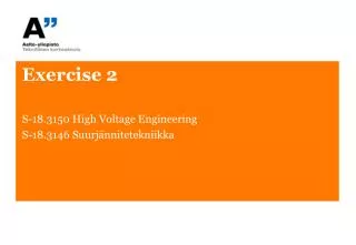
450 400 350 300 250 U50 [kV] 200 150 d=20 mm 100 D=54 mm 50 d 0 D 0 1 2 3 4 5 6 7 8 p [bar] Question 1 • The figure depicts average breakdown voltage (U50) as function of gas pressure (p) for a coaxial SF6 insulator. The structure was originally designed for 6 bar. However, it became apparent that it wasn’t economically efficient to design the system for such high pressures. For this reason, pressure was decreased to 4 bar. Design the structure again so that the 50% breakdown voltage and the ratio D/d remains the same. What are the new D and d parameters? Assume constant electric field strength.
d=20 mm D=54 mm d D 450 Average breakdown voltage: 400 350 300 (original) 250 U50 [kV] 200 (reduced) 150 100 50 0 0 1 2 3 4 5 6 7 8 Coaxial Geometry: p [bar]
Breakdown field strength, p = 4 bar: Assume critical field strength remains constant Denote d´= new inner conductor diameter
Fixed ratio: New outer diameter: 6 bar: D = 54 mm d = 20 mm ∆ = 34 mm 4 bar: D´= 71 mm d´= 26 mm ∆ = 45 mm Although, the ratio D/d remains the same, distance between electrodes has increased. • Originally, breakdown at 4 bar would have occurred at 280 kV. With the new increased distance, voltage has to increase to 370 kV for breakdown to occur Thus, breakdown voltage level has stayed the same compared to original structure.
100 10 U50 [kV] 1 0,1 0,001 0,01 0,1 1 10 pd [bar∙mm] Question 2 • Calculate the onset of partial discharge for the resin test object when breakdown voltage in the cavity obeys Paschen’s law. Pressure in the cavity is 1013 mbar and its dimensions are 1 mm x 5 mm (h x w). Both cavity and the test object are cylindrical. Calculate the apparent charge and consumed energy of the discharge.
f = 30 mm e e = = 4 4 3 mm f = 5 mm r r Three-Capacitance Model: Cb Ca Cc ha hc Cb Voltage is distributed inversely proportional in relation to capacitance:
100 10 U50 [kV] 1 0,1 0,001 0,01 0,1 1 10 pd [bar∙mm] Paschen’s Law: Ub = f(pd) p =1013 mbar, d =1 mm Inception voltage of discharge in cavity uci = 4.5 kV • Inception voltage (applied voltage required to ignite discharge in cavity) ui = 1.5∙ uci= 6.75 kV ≈ 6.8 kV
Discharge is much faster than the feeding circuit (external circuit is too slow to react to discharge circuit can be removed) During discharge, from the point of view of Cc representing the capacitance in the void, the rapid change in voltage is distributed between the series connection of Cb and Ca which are now in parallel with Cc ~ C´a ∆ uc Cc Cb • Calculating apparent charge: Extinction voltage = 0 V Assuming • Apparent charge:
Calculating energy: where q = 1.6 nC and u = ui = 6.8 kV Consumed energy during discharge:
Question 3 • The system in question 2 has 50 Hz alternating voltage of 6 kVRMS. Pressure in the cavity is 1013 mbar. Breakdown voltage in the cavity obeys Paschen’s law and the extinction voltage is 0.5 kV. Draw the voltage waveform and calculate the steady state partial discharge frequency.
Applied voltage where U = 6 kV Voltageovercavity: Inceptionvoltage: Extinctionvoltage:
8 u(t) uc(t) 6 +uci 4 2 +uce 0 -uce -2 -uci -4 -6 Number of discharges per period · 50 Hz Discharge frequency = 4 · 50 Hz = 200 Hz = -8
Question 4 1 2 • The figure shows a bushing (feed-through insulator). Cylinder 1 is the bushing conductor. Insulation layers 2, 3, and 4 have thin metal sheets between them to improve dielectric strength. Design lengths l2 and l3 so that maximum field strength in both sheets is of the same magnitude. What is this maximum field strength value? 3 4 l l l l l l 4 4 3 3 2 2 D 1 D 2 D1 = 20 mm D2 = 34 mm D3 = 48 mm D4 = 62 mm L4 = 140 mm U14 = 30 kV D 3 D 4
Electric field for a cylinder: l Design lengths l2 and l3 so that maximum field strength in both sheets is of the same magnitude 2 1 3 4 l l l l l l 4 4 3 3 2 2 r r U U D1 1 R D 2 l4 and D1…4 are given: D 3 D 4
Voltage: 2 1 3 4 l l l l l l 4 4 3 3 2 2 D1 1 D 2 D 3 D 4