ELECTRONICS CIRCUITS II
ELECTRONICS CIRCUITS II. BY- PANKAJ JAIN ARON COLLEGE GUNA. RC COUPLED AMPLIFIER. RC COUPLED AMPLIFIER. RC coupled amplifier is a common emitter transistor amplifier configuration. RC coupled amplifier can be designed by using potential divider biasing circuit.

ELECTRONICS CIRCUITS II
E N D
Presentation Transcript
ELECTRONICS CIRCUITS II BY- PANKAJ JAIN ARON COLLEGE GUNA
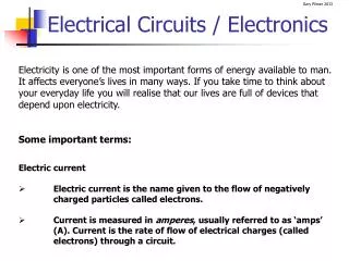
RC COUPLED AMPLIFIER • RC coupled amplifier is a common emitter transistor amplifier configuration. • RC coupled amplifier can be designed by using potential divider biasing circuit. • RC coupled amplifier can be used as voltage amplifier. • The o/p of RC coupled amplifier is simply taken from collector. • The coupling used is RC coupling.
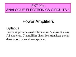
RC COUPLED AMPLIFIER (Cntd..) • RC coupled amplifier is a medium frequency amplifier. • R1,R2 combination provides the base current. • RE is used for bias stabilization. • CE is used to by pass the ac components developed across RE. • RC is the collector resistor and it act as a load.
RC COUPLED AMPLIFIER(Cntd..) VCC • Circuit Diagram RC O/P R1 CC CC I/P CE R2 RE
RC COUPLED AMPLIFIER(Cntd..) • The voltage gain of RC coupled amplifier is grater than unity. • The Q point of the transistor must fix in the centre of the active region/Load line. • For that ,fix VCEQ=50% VCC and • IERE= 10% VCC ICRC= 40% VCC
RC COUPLED AMPLIFIER(Cntd..) • LOAD LINE VCC/(RC+RE) Q POINT ICQ VCEQ VCC
RC COUPLED AMPLIFIER(Cntd..) • h parameter equivalentcircuit • To draw the h parameter equivalent circuit, • Draw the AC behavior of the circuit • AC behavior of a circuit • Open circuit all capacitors. • Short circuit all DC power supply.
RC COUPLED AMPLIFIER(Cntd..) VCC I/P O/P
RC COUPLED AMPLIFIER(Cntd..) • AC behavior of a circuit R1 R2 RC
RC COUPLED AMPLIFIER(Cntd..) • h parameter equivalentcircuit hie hfeib + 1/hoe R1 hrevce RC R2 -
RC COUPLED AMPLIFIER(Cntd..) Simplified h parameter equivalentcircuit R1,R2>>hie so R1//R2//hie=hie hre Vce is a very small voltage , so it is neglected. 1/hoe//RC=RC Now ckt becomes
RC COUPLED AMPLIFIER(Cntd..) Simplified h parameter equivalentcircuit hie hfeib I/P RC
RC COUPLED AMPLIFIER(Cntd..) Frequency Response Gain BW f1 f1 Frequency
RC COUPLED AMPLIFIER(Cntd..) • If we express gain in db, frequency response will be Max Gain in db 3db Gain BW f1 Frequency f1
RC COUPLED AMPLIFIER(Cntd..) Design Assume VCC,IC,β O/P Loop equation VCC=ICRC +VCE+IERE VCE=50% VCC, ICRC=40% VCC Assume that Ic=IE IERE=10% VCC I/P Loop equation IC= β IB VCC=10 IB R1+VBE+IERE ; 9IB R2=VBE+IERE R1=VCC –VBE - IERE/ 10 IB ;R2=VBE+IERE/ 9IB