TPC Alarm Handler Configuration and Usage Guide
Learn how to set up and use the TPC alarm handler for monitoring crucial variables in the system. Understand alarm limits, preferences, snooze functions, and troubleshooting tips.

TPC Alarm Handler Configuration and Usage Guide
E N D
Presentation Transcript
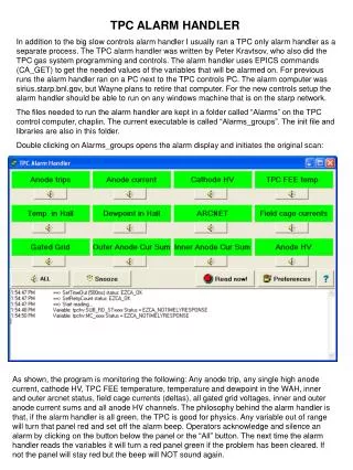
TPC ALARM HANDLER In addition to the big slow controls alarm handler I usually ran a TPC only alarm handler as a separate process. The TPC alarm handler was written by Peter Kravtsov, who also did the TPC gas system programming and controls. The alarm handler uses EPICS commands (CA_GET) to get the needed values of the variables that will be alarmed on. For previous runs the alarm handler ran on a PC next to the TPC controls PC. The alarm computer was sirius.starp.bnl.gov, but Wayne plans to retire that computer. For the new controls setup the alarm handler should be able to run on any windows machine that is on the starp network. The files needed to run the alarm handler are kept in a folder called “Alarms” on the TPC control computer, chaplin. The current executable is called “Alarms_groups”. The init file and libraries are also in this folder. Double clicking on Alarms_groups opens the alarm display and initiates the original scan: As shown, the program is monitoring the following: Any anode trip, any single high anode current, cathode HV, TPC FEE temperature, temperature and dewpoint in the WAH, inner and outer arcnet status, field cage currents (deltas), all gated grid voltages, inner and outer anode current sums and all anode HV channels. The philosophy behind the alarm handler is that, if the alarm handler is all green, the TPC is good for physics. Any variable out of range will turn that panel red and set off the alarm beep. Operators acknowledge and silence an alarm by clicking on the button below the panel or the “All” button. The next time the alarm handler reads the variables it will turn a red panel green if the problem has been cleared. If not the panel will stay red but the beep will NOT sound again.
One can change alarms limits and sampling frequency by clicking on the “Preferences” button: As shown, the current sampling frequency is 120 sec. There is also a “Snooze” button which puts the program to sleep for the designated time (currently 15 minutes). This is useful to prevent recurrent alarms when the TPC is ramping up to physics voltage. Note also that the program will alarm and show a grey panel if it was unable to get the needed variable – this could happen if a VME processor is rebooting, for instance. Some important alarm limits to note from the preferences: A high anode current is set to alarms at .150 microamps The cathode HV must be above 25 kV The WAH temperature is set to 85 deg F – this was set this high last June. The dew point is set to 61 – if modified chilled water is 63 this will give some notice if condensation is possible. The field cage current deltas are set to 400 nA (yellow) and 450 (red). A shorted stripe is ~ 420 nA. These limits should be lowered since the IFCE problem was fixed. The inner anode current sum is 8 microamp (yellow) and 9 (red). This may need to be adjusted Up for DAQ 1000 and AuAu running.
You can change these limits by entering the new values and hitting enter and exiting the preferences GUI by clicking on the “OK” button. Note that some of these alarms are set up to alarm on a binary flag. Thus if ANY anode channel trips a flag is set to 1 and the alarm handler will alarm, since the threshold is set to 0.9. Note that the logic for this alarm handler is slightly different from the slow controls alarm handler (which is looking at some of the same variables.) Since the TPC alarm handler is designed to show “GREEN” for physics running, it will normally show two red “alarms” when the TPC is off between fills ( Anode HV and Cathode HV) This sometimes confuses the detector operators since the TPC shows alarms in the off state.