MODELING FLOW IN LOCK MANIFOLDS
MODELING FLOW IN LOCK MANIFOLDS. Richard L. Stockstill, Jane M. Vaughan, and E. Allen Hammack U.S. Army Engineer Research and Development Center Coastal and Hydraulics Laboratory. Evaluation of Lock Manifolds.

MODELING FLOW IN LOCK MANIFOLDS
E N D
Presentation Transcript
MODELING FLOW IN LOCK MANIFOLDS Richard L. Stockstill, Jane M. Vaughan, and E. Allen Hammack U.S. Army Engineer Research and Development Center Coastal and Hydraulics Laboratory
Evaluation of Lock Manifolds • Hydraulic design of navigation locks depends on knowledge of the performance of particular components. • Performance measures are often times quantified with coefficients such as discharge coefficient or energy loss coefficient. • Lock components are such things as manifolds, gates, and valves. • Manifolds vary in function from intakes to filling and emptying manifolds to outlets.
Filling and Emptying Manifolds In-Chamber Longitudinal Culvert System Side-Port System
Common Manifolds Culvert Locations for the Side-Port and ILCS Filling and Emptying Systems
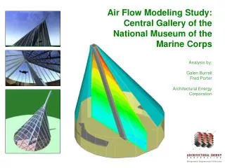
Computational Model of Cannelton Lock – Ohio River Physical and Numerical Models
ILCS Single PortLaboratory Tests Port A Port B
ILCS Single PortComputational Model Computational Model Simulated what was previously Tested in a Physical Model
Single Port Computational Model Computational Mesh Velocity Contours
ILCS Port Single Port Loss Coefficients: Numerical and Laboratory Model Results • Turbulence Models: • k-e and k-w results compared well with lab data • k-erealizable gave loss coefficients that were an order of magnitude higher than lab data
Physical Model Manifold Data Lock 25 Wall Manifold (Left Wall) 1/8 in. diameter pitot tube (Dwyer Instruments model 166)
Loss Through PortCulvert Velocity Head Lock 25 Single Port Loss Across the PortCulvert Velocity Head Loss Through PortPort Velocity Head
Conclusions • Loss coefficients can be determined using detailed 3D computational models. • Calculation of flow in lock manifolds using energy equations relies on accurate loss coefficient data. • Problem is very nonlinear because the coefficients are dependent on an unknown variable, velocity (which is nonlinear). • Understanding of effective use of 3D computational models is on-going