Download
1 / 17
230 likes | 571 Vues
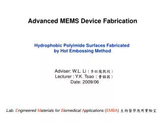
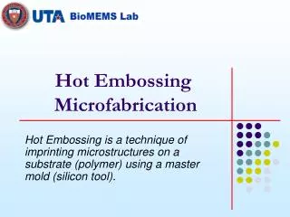
Hot Embossing Microfabrication. Hot Embossing is a technique of imprinting microstructures on a substrate (polymer) using a master mold (silicon tool). Cool the substrate and mold to just below T g. De-embossing of the mold and substrate. Master/Mold from Femto- Second Laser.

E N D
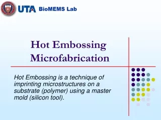
Hot Embossing Microfabrication Hot Embossing is a technique of imprinting microstructures on a substrate (polymer) using a master mold (silicon tool).
Cool the substrate and mold to just below Tg De-embossing of the mold and substrate Master/Mold from Femto- Second Laser Heat the substrate and mold to just above Tg of the substrate Apply embossing force on the substrate via the mold under vacuum Steps in Hot Embossing • Heating Silicon & Polymer above glass transition temperature (Tg). • Applying load by pressing the silicon tool on polymer at certain embossing pressure. • Cooling the silicon tool and polymer assembly below Tg and de-embossing the tool.
Advantages of Hot Embossing System • Cost effective – Easy manufacturability. • Time efficient – Fast process. • Fabrication ofhigh aspect ratio features. • Bio-Compatible surfaces – Polymer substrates used. • Disposable – Low cost for volume production.
Applications of Hot Embossing • BioMEMS/Bio-Sensors • Micro-Fluidic Devices • Micro-Optics • m-TAS (Micro Total Analysis Systems)
Parametric study to determine number of cartridges Parametric study to determine heating block thickness Heating Subsystem: Thermal Analysis • Heating block dimensions and number of cartridges found by a parametric study. • 53 heating cartridges (1 kW, Ø 1/2”, 10” long) on each heating block of 10” (L) x 10.5 (B) x 4” (H).
Heating Subsystem: Thermal Analysis (Cont..) • Appropriate zone configuration of heating cartridges for • optimal heating time, • prevention of hot spots, and • uniform heating on mold and substrate surfaces. • 5 heating zones per heating block having different heating power/heat flux.
Heating Subsystem: Thermal Analysis (Cont..) • Zone Configuration obtained using iterative transient FEM thermal analysis in ANSYS. • Transient behavior of heating cartridges also taken into account.
Forcing Subsystem: Structural Analysis • Forcing System used to provide embossing force. • Forcing provided by a Dual Column Floor Mounted Frame material testing system by Instron Corporation model 5800. • Thermal solution incorporated for FEM structural analysis. • Material modeling incorporates Young’s modulus and Poisson’s ratio variation with temperature.
Forcing Subsystem: Structural Analysis (Cont..) • 1/4th model used for finite element analysis due to symmetry. Displacement contour plot from structural analysis
Cooling Subsystem • 15 Ton (52.76 kW) chiller and Temperature Controller used to cool the system within 2 minutes. • Cooling plates divided into 5 zones (5 inputs, 5 outputs) to obtain • uniform temperature distribution on the mold and substrate surfaces. • optimize cooling time. • Manifolds and flow-meters used to evenly distribute the cooling oil into the cooling plates.
Mini-Vacuum Chamber • Mini vacuum chamber used to provide a clean and moisture free environment during embossing. • Mini vacuum chamber can accommodate an 8” substrate.
Control Subsystem • Compact Fieldpoint system and LabVIEW by National Instruments used for data acquisition and control of the main system and individual sub-system.
Control Subsystem (Cont..) • LabVIEW is used to: • Monitor • the chiller set-points, • the temperature across the master and the substrate, • the pressure in the vacuum chamber. • Control • the motion (displacement and velocity) of the embossing machine, • the flow of the cooling oil through the cooling block, • the current through the heater cartridges • relief valve of the vacuum chamber.