Download
1 / 15
150 likes | 198 Vues
Learn the correct methods for dimensioning objects in technical drawings, including avoiding crossing extension lines and dimension lines, using leader lines, and understanding diameter versus radius. Avoid common dimensioning errors such as unnecessary dimensions, duplicate dimensions, dimensioning to hidden lines, and true scale inaccuracies.

E N D
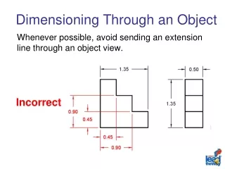
Dimensioning Through an Object Whenever possible, avoid sending an extension line through an object view. Incorrect
Crossing Extension Lines Whenever possible, avoid crossing extension lines. Incorrect
Crossing Dimension Lines Never cross a dimension line with another dimension line or an extension line. Incorrect
Leader Line Conventions • Leader Line Definition • Leader Line Angles • Diameter versus Radius • Hole and Cylinder Dimensions
Terminology Leader A leader is a thin, solid line used to indicate features with which a dimension, note, or symbol is associated. • Points toward the center of the feature • Arrow on one end touches the part or detail • Text is extended from a short horizontal line or “shoulder” on the other end
Leader Line Angles Whenever possible, a leader line dimension should occur at approximately 30°, 45°, or 60° from the horizontal or vertical. Leaders should never be drawn horizontally or vertically
Diameter versus Radius A complete circular object is called out by its diameter. A fillet or arc is identified by its arc radius.
Hole and Cylinder Dimensions A hole is dimensioned on a view showing its true circular shape. A leader should be used for this purpose. A cylinder, or solid cylindrical feature, is dimensioned on a side view using a linear dimension.
Common Dimensioning Errors • Unnecessary Dimensions • Duplicate Dimensions • Dimensioning to Hidden Lines • True Scale
Unnecessary Dimensions A drawing must contain only those dimensions that are necessary to define the object’s geometry. Incorrect
Duplicate Dimensions Do not call out the same dimension on more than one view. Incorrect
Dimensioning to Hidden Lines Never dimension to hidden lines. If necessary, generate an alternate view, or section view, where the feature appears as an object line.
True Scale Dimensions should reflect an object’s actual size; not its scaled size.
References Bertoline, G. R., & Wiebe, E. N. (2003). Technical graphics communication (3rd ed.). NY: McGraw-Hill Companies, Inc. Lockhart, S., & Johnson, C. (2000). Engineering design communication. Upper Saddle River, NJ: Prentice Hall Inc. Madsen D. A., Folkestad, J., Schertz, K. A., Shumaker, T. M., Stark, C., & Turpin, J. L. (2004). Engineering drawing and design (3rd ed.). Albany, NY: Delmar-Thompson Learning. Spence, W. P. (1991). Drafting technology and practice (3rd ed.). NY: Glencoe-McGraw Hill Inc. Wallach, P. (2003). Fundamental of modern drafting. Clifton Park, NY: Thomson Delmar Learning.
Credits: Writer: Terry C. Nagy Jr. Lesson Editor: Ed Hughes Narration: CJ Amarosa Production: CJ Amarosa