Maximizing Benefits of MIG Welding Techniques
980 likes | 1k Vues
Learn about Metal Inert Gas (MIG) welding advantages, equipment, and techniques. Understand MIG welding process and applications in metal fabrication. Explore MIG welding benefits and procedures.

Maximizing Benefits of MIG Welding Techniques
E N D
Presentation Transcript
Lesson 7 Applying Metal Inert Gas (MIG) Welding Techniques
Next Generation Science/Common Core Standards Addressed! • CCSS.ELALiteracy.RST.9‐10.1 Cite specific textual evidence to support analysis of science and technical texts, attending to the precise details of explanations or descriptions. • CCSS.ELALiteracy.RST.9‐10.3 Follow precisely a complex multistep procedure when carrying out experiments, taking measurements, or performing technical tasks, attending to special cases or exceptions defined in the text. • CCSS.Math.Content.HSGCO.D.12 Make formal geometric constructions with a variety of tools and methods (compass and straightedge, string, reflective devices, paper folding, dynamic geometric software, etc.). Copying a segment; copying an angle; bisecting a segment; bisecting an angle; constructing perpendicular lines, including the perpendicular bisector of a line segment; and constructing a line parallel to a given line through a point not on the line.
Agriculture, Food and Natural Resource Standards Addressed! • PST.01.03. Apply physical science principles to metal fabrication using a variety of welding and cutting processes (e.g., SMAW, GMAW, GTAW, fuel-oxygen and plasma arc torch, etc.). • PST.01.03.01.c. Evaluate the quality of metal fabrication procedures (e.g., SMAW, GMAW, GTAW, fuel-oxygen and plasma arc torch, etc.).
Bell Work! • 1. Explain the advantages of the metal inert gas (MIG) welding process. • 2. Describe the equipment, types of shielding gases, and electrodes used in the MIG welding process. • 3. Describe the types of metal transfer patterns used in MIG welding and relate their applications. • 4. What are the advantages of MIG welding?
Terms • Spray arc transfer • Stickout • Transition current • Travel angle • Whiskers • Burnback • Ductility • Globular transfer • Inert gas • Short arc transfer
Interest Approach • Have you heard the term MIG Welding • What are the advantages of MIG Welding? • How is MIG Welding done?
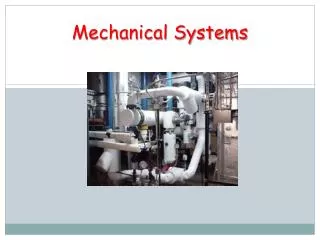
Metal inert gas welding (MIG) is a process in which a consumable wire electrode is fed into an arc and weld pool at a steady but adjustable rate, while a continuous envelope of inert gas flows out around the wire and shields the weld from contamination by the atmosphere.
The MIG welding process has several advantages which account for its popularity and increased use in the welding industries.
MIG Welding Advantages • A. Welding jobs can be performed faster with the MIG process. The continuous wire feed eliminates the need to change electrodes.
MIG Welding Advantages • B. Weld cleaning and preparation time is less for MIG welding than for stick electrode welds. Since the gaseous shield protects the molten metal from the atmospheric gases, there is no flux or slag, and spatter is minimal. • C. Less time is required to teach individuals how to MIG weld. If an individual has learned how to stick weld they can pick up on MIG welding quickly.
MIG Welding Advantages • D. Because of the fast travel speed at which MIG welding can be done, there is a smaller heat-affected zone than with the shielded metal arc welding process. The smaller heat-affected zone results in less grain growth, less distortion, and less loss of temper in the base metal.
MIG Welding Advantages • E. Both thick and thin metals can be welded successfully and economically with the MIG process. • F. Less time is needed to prepare weld joints since the MIG welds are deep penetrating. Narrow weld joints can be used with MIG welding and still secure sound weldments.
MIG Welding Advantages • G. The MIG welding process can be used to join both ferrous and nonferrous metals. The development of electrode wire and the use of spool guns has made the MIG process widely used for aluminum, stainless steel, high-carbon-steel, and alloy-steel fabrication. Simply change the wire and shielding gas to adapt to different types of metal.
MIG Welding Advantages • H. The weld visibility is generally good. There is less smoke and fumes so operator environment is improved and it is easier to see the weld formation.
What equipment, types of shielding gases, and electrodes are used in the MIG welding process?
To understand the MIG welding process, you must understand the equipment needed. It consists of a welder, a wire feed system, cable and welding gun assembly, shielding gas supply, and electrode wire.
MIG Welders • A. Most welders used for MIG welding are direct current machines of the constant voltage type. • B. MIG welding machines must be designed to produce a constant voltage. With a constant voltage MIG machine, the output voltage will change very little with large changes in current.
MIG Welders • C. Welding voltage has an effect on bead width, spatter, undercutting, and penetration. • D. The constant voltage welding machines are designed so that when the arc voltage changes, the arc current is automatically adjusted or self-corrected. • WFS + wire feed speed
E. Most MIG welding units have three adjustments which must be in balance to achieve a quality weld. These are voltage control, wire feed speed, and shielding gas flow rate.
Wire Feeder • 1. The wire feeder continually draws a small diameter electrode wire from the spool and drives it through the cable assembly and gun at a constant rate of speed. • 2. The constant rate of wire feed is necessary to assure a smooth even arc. This must be adjustable to provide for different welding current settings that may be desired.
Wire Feeder • 3. Wire speed varies with the metal thickness being welded, type of joint, and position of the weld.
Wire Feeder F. To move the electrode wire from the spool to the MIG welding gun, run the wire through a conduit and system of drive wheels. • These drive wheels, depending upon their location in the wire feed unit, are either the push type or the pull type.
Wire Feeder F1. The pull-type drive wheels are located relatively close to the MIG gun and exert a pulling action on the wire. • Pull-type drive wheels are used on most spool guns. 2. With the push-type drive wheels, the wire goes through the wheels and is pushed through the electrode lead and out through the MIG gun.
G. Correct tension on the wire feed drive wheels is very important. • 1. Too little tension results in drive wheel slippage which causes the wire to be fed into the puddle at an uneven rate, giving a poor-quality weld.
G. Correct tension on the wire feed drive wheels is very important. 2. Too much tension on the wire feed wheels results in deformation of the wire shape. • This altered wire shape can make it difficult to thread the electrode through the conduit and the contact tip in the MIG gun.
H. When a blockage or burnback occurs, the MIG gun should be turned off immediately to prevent entanglement. • A burnback occurs when the electrode wire is fused to the contact tip. I. The wire feeders have different sized drive rolls so they can accommodate different sizes and types of wire.
MIG Gun J. The electrode holder is commonly referred to as the MIG gun. • The MIG gun has a trigger switch for activating the welding operation, a gas nozzle for directing the flow of the shielding gas, and a contact tip.
MIG Gun J1. The nozzle on the MIG gun directs the shielding gas over the puddle during welding. • A nozzle that is too large or too small may result in air from the atmosphere reaching the puddle and contaminating the weld. • 2. The nozzle is made of copper alloy to help remove the heat from the welding zone.
K. When welding outside, where the weld zone is subjected to drafts and wind currents, the flow of shielding gas needs to be strong enough so that drafts do not blow the shielding gas from the weld zone. Removal of shielding gases by the wind will lead to contaminated, weakened welds.
L. The contact tip helps to guide the wire electrode into the puddle as well as transmit the weld current to the electrode wire. • The electrode wire actually touches the contact tip as it is fed through the MIG gun. • During this contact, the weld current is transmitted to the electrode. The tip must match the wire diameter being used in the welder.
M. Shielding Gas The shielding gas displaces the atmospheric air with a cover of protective gas. • The welding arc is then struck under the shielding gas cover and the molten puddle is not contaminated by the elements in the atmosphere
M. Shielding Gas Inert and non-inert gases are used for shielding in MIG welding. • An inert gas is one whose atoms are very stable and will not react easily with atoms of other elements.
1. Argon Has a low ionization potential and therefore creates a very stable arc when used as a shielding gas. The arc is quiet and smooth sounding and has very little spatter. • a. Argon is a good shielding gas for welding sheet metal and thin metal sections.Pure argon is also used for welding aluminum, copper, magnesium, and nickel. • b. Pure argon is not recommended for use on carbon steels.
2. Helium gas • Conducts heat well and is preferred for welding thick metal stock. It is good for welding metals that conduct heat well, such as aluminum, copper, and magnesium. • a. Helium requires higher arc voltages than argon. • b. Helium-shielded welds are wider, have less penetration and more spatter than argon-shielded welds. • C. Helium is quite often used along with flux cored MIG welding wire.
3. Carbon dioxide The most often used gas in MIG welding because it gives good bead penetration, wide beads, no undercutting and good bead contour and it costs much less than argon or helium. • a. The main application of carbon dioxide shielding gas is welding low and medium carbon steels. • b. When using carbon dioxide shielding gas, the arc is unstable, which causes a lot of spatter.
3. Carbon dioxide • c. Carbon dioxide gas has a tendency to disassociate. At high temperatures encountered in the arc zone, carbon dioxide will partially break up into oxygen and carbon monoxide. • d. Good ventilation is essential to remove this deadly gas
4. Gas Mixtures • Argon / Oxygen is used quite often when welding stainless steel. The oxygen gas helps to stabilize the arc and eliminate much of the weld splatter.
4. Gas Mixtures • b. An argon-helium mixture is used for welding thick non-ferrous metals. This mixture gives the same arc stability as pure argon with very little spatter, and produces a deep penetrating bead.
4. Gas Mixtures • c. The argon-carbon dioxide mixture is used mainly for carbon steels, low alloy steels, and some stainless steel. The gas mixture helps to stabilize the arc, reduce spatter, eliminate undercutting and improve metal transfer straight through the arc.
N. Gas Cylinder and Gauges • The tank supplying the shielding gas will have a gauge and a gas flowmeter. • The volume of gas directed over the weld zone is regulated by the flowmeter.
O. Electrode Wire The selection of the correct electrode wire is an important decision and the success of the welding operation depends on the correct selection.
O. Electrode Wire There are factors to consider when selecting the correct electrode. • 1. Consider the type of metal to be welded and choose a filler wire to match the base metal in analysis and mechanical properties.
O. Electrode Wire 2. Consider the joint design. • Thicker metals and complicated joint designs usually require filler wires that provide high ductility. • Ductility is the ability to be fashioned into a new form without breaking.
O. Electrode Wire 3. Examine the surface condition of the metal to be welded. • If it is rusty or scaly, it will have an effect on the type of wire selected. 4. Consider the service requirements that the welded product will encounter. 5. MIG welding is not effective on rusty or painted surfaces as the lower voltage is not effective a scouring the surface in the same manner as a stick electrode.
P. Electrode Wire Classification • MIG electrode wire is classified by the American Welding Society (AWS). • An example is ER70S6. • For carbon-steel wire, the “E” identifies it as an electrode • “R” notes that it is a rod • Note – MIG wire is available in different diameters. The diameter of the wire must match the drive wheels and the gun tip.
P. Electrode Wire Classification • The first two digits relate the tensile strength in 1,000 lbs. psi • The “S” signifies the electrode is a solid bare wire • Any remaining number and symbols relate the chemical composition variations of electrodes.
What are the types of metal transfer patterns used in MIG welding and when are they used?