Download
1 / 13
130 likes | 260 Vues
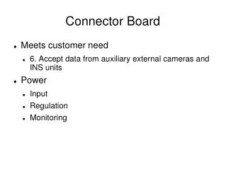
This document outlines the design and implementation of an advanced Connector Board featuring dual GigE and Camera Link interfaces, a 10/100 Ethernet port, and USB connectivity. The board is designed for an Inertial Navigation System (INS) with a focus on various mounting requirements and interface routing strategies. It integrates components such as an Inertial Measurement Unit (IMU) and Global Navigation Satellite System (GNSS) for accurate directional and locational data. It accommodates OEM-specific power requirements and showcases a functional block diagram for clarity.

E N D
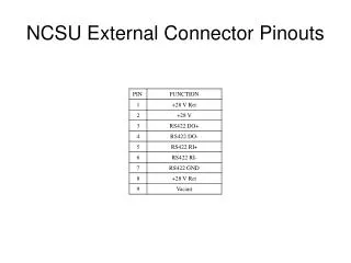
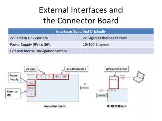
External Interfaces andthe Connector Board 2x GigE 2x Camera Link 10/100 Ethernet Power Supply External INS Connector Board D3 OEM Board
External Interfaces andthe Connector Board Power Supply External INS 2x Camera Link 2x GigE RCA output 10/100 Ethernet USB port Connector Panel
External Interfaces andthe Connector Board • Goal: • All interfaces routed through and mounted on the Connector Board • Reality: • Various different mountings and routings necessary
Interface Routing andConnector Mounting 2x Camera Link External INS Power Supply • 2x Camera Link = nearly full width of Connector Board Connector Panel
Interface Routing andConnector Mounting • GigE mounted on FPGA Board 2x GigE FPGA Board (bottom view) Connector Panel
Interface Routing andConnector Mounting RCA 10/100 Ethernet • RCA and 10/100 Ethernet routed directly to D3 OEM Board 10/100 Ethernet RCA output D3 OEM Board (top view) Connector Panel
Interface Routing andConnector Mounting USB port • USB routed directly to internal GNSS receiver Connector Panel
The Connector Board • Having determined what it needs to do, design could commence Customer Provided Block Diagram
Inertial Navigation System (INS) • Determines: • Direction • Roll, pitch & yaw • Velocity • Inertial Measurement Unit (IMU) • Location • Global Navigation Satellite System (GNSS) • Global Positioning System (GPS) • GLONASS
Global Navigation Satellite System • Customer Specified • NovAtel OEMV-2 or OEMV-3 • RS-232 interface • Different power requirements OEMV-2: 3.3 +5%/-3% VDC OEMV-3: 4.5 to 18 VDC