Download

1 / 15
170 likes | 332 Vues
Pitot Stagnation Tubes Under Laminar Conditions. *P7.24 Jace Benoit February 15, 2007.

E N D
Pitot Stagnation Tubes Under Laminar Conditions *P7.24 Jace Benoit February 15, 2007
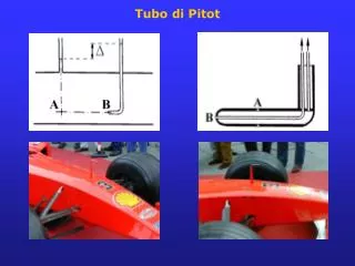
Air at 20°C and 1 atm flows past the flat plate in Fig. P7.24 under laminar conditions. There are two equally spaced pitot stagnation tubes, each placed 2 mm from the wall. The manometer fluid is water at 20°C. If U=15m/s and L=50cm, determine the values of the monometer readings h1and h2. Determine these values if the manometer fluid is replaced with mercury. Problem Statement
Sketch u1 u2 Fig P7.24
Assumptions • Laminar Flat-Plate Flow • Incompressible Flow • Constant Temperature • No Mixing at Liquid-Air Interface • Frictionless Flow • Steady Flow
Solution The following gives a summary of the densities and kinematic velocity from tables A.1, A.2, and A.3.
Solution Since this is laminar flow along a boundary layer, the Blasius equation (7.21) can be used to determine η.
Solution Now that η is known, Table 7.1 on page 462 can be used to approximate u/U. For η = 2.8, u/U = 0.81152 and for η = 3.0, u/U = 0.84605, so for η1 = 2.828: Fortunately, the u/U value corresponding to η = 2.0 can be read directly from Table 7.1 to be 0.62997.
Solution Plugging U = 15 m/s into the u/U expression yields the velocities at the entrances of each manometer.
Solution With the inlet velocities known, Bernoulli’s equation (3.77) can be used to solve for the inlet pressure assuming atmospheric pressure at the outlet of the manometer.
Solution Rearranging this equations with the appropriate cancellations yields the following:
Solution Now that the inlet and outlet pressures are known, this problem can now be solved as a manometer problem.
Solution Finally, the manometer heights for water are as follows:
Solution All that needs to be done to determine the height if mercury is the manometer fluid is changed the density in the previous equation to 13,550 kg/m3.
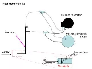
Application to BME The manometer with one end being submerged in water and the other in another medium can mimic a catheter which is used to measure various biological effects such as cardiac output and blood pressure. The catheter is filled with a saline solution similar to how this manometer is filled with water and mercury, and pressure is exerted at each ends of the catheter.
Reference White, Frank M. Fluid Mechanics. 5th Ed. McGraw-Hill Companies, Inc.: New York. 2003.