BALLBOT PROTOTYPE DESIGN REVIEW
BALLBOT PROTOTYPE DESIGN REVIEW. Brian Kosoris Jeroen Waning Bahati Gitego Yuriy Psarev. MTRE 4400 10/11/2011. System Overview. Mechanical Structure Base Vertical structure Landing gear Electronics Sensors Actuators/motors MCU CPU Control System State-space variable model

BALLBOT PROTOTYPE DESIGN REVIEW
E N D
Presentation Transcript
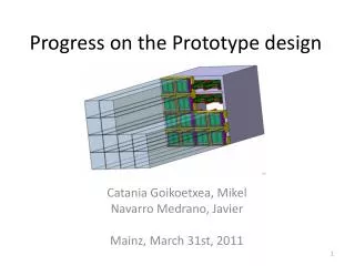
BALLBOTPROTOTYPE DESIGN REVIEW Brian Kosoris Jeroen Waning BahatiGitego YuriyPsarev MTRE 4400 10/11/2011
System Overview • Mechanical Structure • Base • Vertical structure • Landing gear • Electronics • Sensors • Actuators/motors • MCU • CPU • Control System • State-space variable model • MatLab/Simulink model • Synthesis of 3D motion
Mechanical Design (CAD) • Base • Critical mechanism • Mechanical function impacts success • Aluminum vs. steel? • Feasibility • Cost • Workability • Aesthetics • Strength/rigidity vs. weight • Two perpendicular pairs of motors (@ 45’s) • Built in damper for vertical disturbances
Wheel Base • Design Concept • Four compound wheels perpendicular to each axis • Each wheel oriented 45 Degrees • Metal chassis • Motors mounted and coupled to the wheels • Design and Material Requirements • Robust • Load Bearing, material cannot deform under any circumstance • Fairly practical and inexpensive to fabricate • Effectively transfer load from wheels to chassis • Minimal vibrations • Lightweight
Materials Specifications • Fasteners • Aluminum Alloy ¼” D, 3/8” L, Dome head, Mil-spec Rivets • Structural 6061 T6 Aluminum • Available Locally • Very strong for its weight • Easy to work with and machinable • Available in beams, channels, angles, square and rectangular beams, pipes, etc • ultimate tensile strength of at least 42,000 psi (290 MPa) • yield strength of at least 35,000 psi (241 MPa)
Base Assembly (CAD Model) Top View Bottom View
Structural Design • Vertical structure • Simple aluminum frame • Multiple modular-plateau design • Houses main CPU, IMU board, power supply, etc. • Modular/adjustable for optimization • Facilitates testing phase • Adjustable center of mass • Serves as a three-dimensional inverted pendulum • Bolt-able design for quick adjustments
Structural Design • Design Concept • 2ft tall • Structural tier system with 5 levels • Each level will be octagonal shaped sheet metal • Metal chassis • Design Requirements • Robust • Load Bearing • Fairly Practical and inexpensive to fabricate • Modular and Accessible • For ease of adding, removing and modifying components • Very accessible • Lightweight
Structural Design • Materials • .125” 6061 T-6 Aluminum Sheet metal • 1.5”x 1” x .125” Aluminum Channel • 2”x2” Angle Aluminum • Specifications • 9”x9”x24” tall • Minimum success criteria • Balance structure on ball • Wheel base goes here
Fabrication Progress ** NOTE: Only a sample of what has been done
Extraneous Concept Design (CAD Model) • Landing gear • Supplemental ‘fail-safe’ design • Protects investment • Backup if minimum success criteria is not met • i.e. BallBot topples over • Simple & effective • Worm-screw actuator design • Encapsulates ball when BallBot is balanced
Electrical Components • New components • Micro ITX gigabyte board • High-level CPU to run MatLab • Processes integer data from IMU board • Runs control algorithm to digest sensor data • Provides output to motor controllers • 100% onboard control for self-sufficiency • A321 batteries x 30 for onboard power supply • Provides 12-16.5V (3-5A) to motors • Provides 5V for digital logic (IMU board and CPU)
Micro ITX onboard Computer • 1.6GHz CPU • 4GB DDR3 • Windows 7 • MatLab 2010 • Rotational matrix manipulation • State-space matrix processing
IMU Board • Arduino ATmega2560 • Microcontroller/microprocessor • ADXL345 Accelerometer • Three-axis acceleration measurement unit • IDG500 Gyroscope • Two-axis angular velocity measurement unit • Provides real-time feedback of inertial orientation/rotation in 3D space
Sensor Data Processing • IMU data will be relayed to onboard computer • MatLab will process complex state-space equations and rotational matrices • Control system theory is used to model the system for analysis of stability • Robotics synthesis • Rotational matrices synthesize the robots orientation and angular velocity • MatLab will process the matrices to provide feedback to the Arduino which sends signals to the motor controllers
Mathematical Modeling • To model the inverted spherical pendulum we will first have to simplify and linearize the BallBot model • The angle of the body makes with the vertical axis relatively close to zero. • With this assumption, the inverted spherical pendulum can be decoupled into two identical inverted pendulum measurable in the XZ and YZ plane
Mathematical Modeling • A mathematical model of the Spherical Inverted pendulum will be derived using the Lagrange-Euler method. • Lagrange-Euler Method relies on the energy property of the system • The Lagrange-Euler equation is defined as follow: , • L is the Lagrange function. • T is the kinetics energy of the mechanical system. • U is the potential energy of the system.
Deriving the Position and Velocity Equation of the Spherical Inverted pendulum • Equation 1 • Equation 2 • Equation 3 • Equation 4
Kinetic Energy And Potential Energy of the System • Equation 5 • Equation 6 • Equation 7 • Equation 8 • = mass of the spherical wheel. • = mass of the body • Inertial moment of the spherical wheel • = inertial moment of the body (pitch) with respect to the body center of mass • = inertial moment of the wheels.
Deriving the force Equation • Taking the derivative of the Euler- Lagrange function express the formula as a force function • Equation 9 • Equation 10 • computing the Lagrange Equation as depicted in equation 9 and equation 10, the following results are obtained: • Equation 11 • Equation 12 .
Relationship between the Force and DC motor Considering the dc motor torque and viscous friction, the following force equation can be derived: Equation 13 Equation 14 = dc motor internal inductance = dc motor back emf constant Assuming the motor inductance to be negligible, current could be expressed as follow: Equation 16 Equation 17
Linearization of The Force Equation • As Mentioned early we will first linearize our force Equation before expressing them as State Space function. • This is done by taking the limit as • Applying the stated method to Equation11 and Equation 12 we get the following: • Equation 20 • Equation 21 • Equation 20 and Equation 21 can further be expressed in the following notation: • Equation 22 • Next step in the state space
Expression of Mathematical Equation in State Space • Next step in the state space modeling process will be defining X as a state, and U as the input with. Next we will express X and U as follow: • Equation 24 • , Equation 25
Controller Simulation • State-space modeling • x’ = Ax + Bu; y = Cx + Du • MatLab A = 0 0 1.0000 0 0 0 0 1.0000 0 -198.9738 -0.0567 0.0567 0 42.8060 0.0092 -0.0092 B = 0 0 0 1 C = 1 0 0 0 D = 0
State-space model (cont.) controllability_matrix = 0 0.61661 -0.040635 19.844 0 -0.099717 0.0065714 -4.2689 0.61661 -0.040635 19.844 -2.6754 -0.099717 0.0065714 -4.2689 0.5025 Controllable_Rank_is = 4 observability_matrix = 1 0 0 0 0 0 1 0 0 -198.97 -0.056727 0.056727 0 13.715 0.0037383 -198.98
State-space model (cont.) Observable_Rank_is = 4 Poles = 0 -6.5686 6.5168 -0.014085 Kd = -36.621 -1698.7 -40.986 -423.26 pole_placement = -14 -5 -240 -180 L = 438.93 -4372.5 51264 -26241 K_f = -0.14086 -886.74 -1.4844 -141.81 K_i = -0.0071253
State-space model (cont.) K_LQR = -0.14086 -886.74 -1.4844 -141.81 -0.0071253 new_A_by_K_gain = 0 0 1 0 0 0 0 0 1 0 0.086857 347.8 0.85855 87.502 0.0043935 -0.014046 -45.618 -0.13884 -14.151 -0.00071051 1 0 0 0 0
Controller Overview • State-space subsystem block diagram
Controller Simulation • Subsystem • Block-diagram representation of inside subsystem
Robot Motion Synthesis • BallBot’s orientation/angular motion can be represented with rotational matrices • Euler angles indicate roll, pitch, and yaw of the BallBot due to disturbances (gravity, wind, push) • Simplifies balancing/stability algorithm
Robot Motion Synthesis • Frame 0 = 00X0Y0Z0 • Frame 1 = 01X1Y1Z1 • Position vector 0 = 3x1 matrix = [0 0 1] T • Position vector 1 = [ ] = 3x1 matrix • The angular velocities ωψ, ωϕ, ωθrepresent the data provided by the IMU board and are integrated to find position
Robot Motion Synthesis • The rotational matrix is very complex in terms of possible orientation synthesis • The axes of frame 0 and frame 1 are compared with the dot product of the components of position vector 0 and position vector 1
Robot Motion Synthesis • All possible orientations: • C1 = Cos(ψ), C2 = Cos(ϕ), C3 = Cos(θ) • S1 = Sin(ψ), S2 = Sin(ϕ), S3 = Sin(θ)
Design Requirements – Major milestones • In this phase of the design: • The mechanical structure must be completed by October 20th, 2011 • Electronics can then be integrated into assembly (October 27th) • Arduino and MatLab communication algorithm (November 2nd) • Begin preliminary testing (October 27th – November 10th) • Finalize complete algorithm (November 16th) • Optimization, aesthetics, minor revisions (November 27th)
Trade Study – Accelerometer Filter • ADXL345 • Capacitor bandwidth filter – band-limiting filter • Noise reduction – (dispose of anomalous data) • Anti-aliasing – (prevent data loss due to resolution change) • X & Y max bandwidth – 1650Hz • Z bandwidth – 550Hz • Minimum capacitance = 0.0047μF
Trade Study – Accelerometer Filter • Bandwidth filter - capacitor selection • Capacitance decides bandwidth • Bandwidth indicates data resolution Table 1 – Bandwidth vs. Capacitance • Cx, Cy, Cz pins on ADXL345 • Low-pass filtering • Noise reduction • 3-dB bandwidth equation • F−3 dB = 1/(2π(32 kΩ) × C(X, Y, Z))
Trade Study – Accelerometer Filter • F−3 dB = 1/(2π(32 kΩ) × C(X, Y, Z)) • Approximates to F–3 dB = 5 μF/C(X, Y, Z) • 1650 Hz = 5 μF/0.00303 μF • Cx = Cy = 0.00303 μF • 550 Hz = 5 μF/0.0091μF • Cz = 0.0091 μF • These capacitor values will provide the highest data resolution for • 1650 readings per second for X and Y acceleration • Detect smallest possible acceleration in planar motion • 550 readings for Z acceleration • The Z axis will thus represent the vertical axis of the BallBot from the center of the ball to the top of the BallBot • Then Z-axis data does not require high resolution
Trade Study – Accelerometer Filter • Rms noise = Noise Density x sqrt(BW) • Noise is thus a factor of bandwidth Table 2 – Noise Density
Trade Study – AccelerometerOperating Voltage • The ADXL345 output is ratio-metric • The output sensitivity (or scale factor) varies proportionally to the supply voltage. • VS = 3.6 V - output sensitivity = 360 mV/g • VS = 2 V - output sensitivity =195 mV/g. • Arduino’s 3v3 pin supplies 3.3V • Sensitivity thus approximates to 320 mV/g to 340 mV/g (or 330 mV/g average) • Sensitivity estimated to be adequate for BallBot • Arduino’s built-in serial monitor read consistent data • Only real-time testing will confirm • ADXL345 can absorb up to 10,000g of force without being damaged – Hopefully not a concern!
Trade Study – AccelerometerOperating Voltage X-Y-Z sensitivity (voltage/gravity) Data Sheet
Extraneous Facilities/Resources • Jeroen’s family workshop • Industrial bandsaw • Computerized lathe • Machine wheel shafts • Complex • Critical
Extraneous Facilities/Resources • Jeroen’s family workshop • Drillmills • 20 ton press • Pneumatic tools • Workbench, vice, small tools, bits, materials, etc. (not seen)
References • Arduino – microcontroller (libraries/tutorials) • www.arduino.cc • SparkFun – sensors/electronics (datasheets) • www.sparkfun.com • MatLab resource (control system toolbox, etc.) • http://www.mathworks.com/matlabcentral/fileexchange/23931 • SolidWorkshelpfile • http://help.solidworks.com/2012/English/SolidWorks/sldworks/r_welcome_sw_online_help.htm • Robot Modeling and Control (textbook) • Control Systems Engineering (textbook)