Download
1 / 12
120 likes | 145 Vues
This project aims to design an endplate for GEM and Micromegas detectors with a focus on feasability, performance, and ion feedback studies. The design includes considerations for amplification, pad geometry, and electronics, aiming for long-term running experience in real conditions while optimizing configuration and materials.

E N D
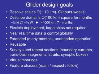
Large prototype goalsEndplate design P. Colas
General ideas • We have to agree first on the goals to understand how to build the endplate • The design should be as close as possible for GEM and Micromegas (requires regular common meetings), but no mix possible • A (small) space should be kept for digital pixel readout (EUDET contract) • The endplate should be a support for several pannels or tiles.
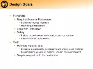
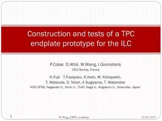
Goals (open for discussion) • What it is: • Demonstrate feasability and performances of the real detector, in particular possibility to cover by modules and to obtain the target resolution and feedback • Study various solutions for amplification, pad geometry, electronics • Gain a long-term experience of running in real conditions • Study distortions (their effect and how to correct them) • What it is not:
Goals (open for discussion) • What it is not: • An apparatus to study in detail gas properties (smaller devices do better for this) • An apparatus for detailed aging studies (special devices will allow testing of various materials and gases in high radiation, already started at Saclay and NIKHEF)
Ion feedback in the LP • Possibility to test the effect of the ‘ion sheet’ (at each beam crossing a fraction of the positive ions flows back to the cathode • What is the effect of such an ion sheet on the electrons drifting from a track? • This can be studied using an UV lamp (as NIKHEF’s Xe lamp) to produce photoelectrons on the foil. • How to do this in practice? UV window? Lamp in the gas volume?
Channel arrangement • 50 cm track length (80 4-mm pads to 40 8-mm long pads) • Transverse pad size : 1mm to 3mm. • For a 5cm wide beam : • 50x80=4000 channels for 1x4 mm pads • To cover the whole surface with 3x8 mm pads, need 10000 channels.
Guidelines for the design • Low weight (for mechanical simplicity) • Low Rad. Thickness (for transparency) • Cooling included • Stiffness (rather low tolerances for Micromegas) • Must work with 7mb pressure difference • Low outgasing and anti-aging materials • Gas tightness
Optimization of the configuration • With David Attié, we studied the possible configurations to have • Identical (interchangeable) modules • Enough boundary configurations (some modules can be dummy, just carrying the right potential) Each ‘tile’ must have its own seal-ring (see Dan Peterson’s drawing)
Options for the Micromegas endplates • Should try the latest kind of ‘bulk’ available at that time • Most likely resistive foils have to be included