Download
1 / 9
90 likes | 112 Vues
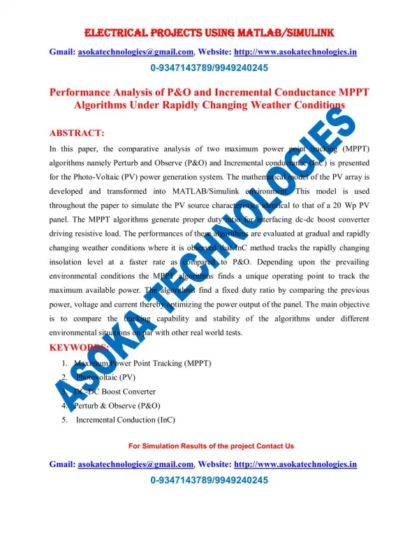
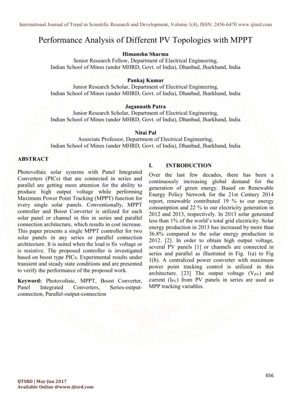
Photovoltaic solar systems with Panel Integrated Converters PICs that are connected in series and parallel are getting more attention for the ability to produce high output voltage while performing Maximum Power Point Tracking MPPT function for every single solar panels. Conventionally, MPPT controller and Boost Converter is utilized for each solar panel or channel in this in series and parallel connection architecture, which results in cost increase. This paper presents a single MPPT controller for two solar panels in any series or parallel connection architecture. It is suited when the load is fix voltage or is resistive. The proposed controller is investigated based on boost type PICs. Experimental results under transient and steady state conditions and are presented to verify the performance of the proposed work. Himanshu Sharma | Pankaj Kumar | Jagannath Patra | Nitai Pal "Performance Analysis of Different PV Topologies with MPPT" Published in International Journal of Trend in Scientific Research and Development (ijtsrd), ISSN: 2456-6470, Volume-1 | Issue-4 , June 2017, URL: https://www.ijtsrd.com/papers/ijtsrd2185.pdf Paper URL: http://www.ijtsrd.com/engineering/electrical-engineering/2185/performance-analysis-of-different-pv-topologies-with-mppt/himanshu-sharma<br>

E N D
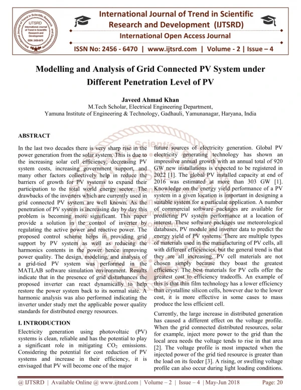
International Journal of Trend in Scientific Research and Development, Volume 1(4), ISSN: 2456-6470 www.ijtsrd.com Performance Analysis of Different PV Topologies with MPPT Himanshu Sharma Senior Research Fellow, Department of Electrical Engineering, Indian School of Mines (under MHRD, Govt. of India), Dhanbad, Jharkhand, India Pankaj Kumar Junior Research Scholar, Department of Electrical Engineering, Indian School of Mines (under MHRD, Govt. of India), Dhanbad, Jharkhand, India Jagannath Patra Junior Research Scholar, Department of Electrical Engineering, Indian School of Mines (under MHRD, Govt. of India), Dhanbad, Jharkhand, India Nitai Pal Associate Professor, Department of Electrical Engineering, Indian School of Mines (under MHRD, Govt. of India), Dhanbad, Jharkhand, India ABSTRACT Photovoltaic solar systems with Panel Integrated Converters (PICs) that are connected in series and parallel are getting more attention for the ability to produce high output voltage while performing Maximum Power Point Tracking (MPPT) function for every single solar panels. Conventionally, MPPT controller and Boost Converter is utilized for each solar panel or channel in this in series and parallel connection architecture, which results in cost increase. This paper presents a single MPPT controller for two solar panels in any series or parallel connection architecture. It is suited when the load is fix voltage or is resistive. The proposed controller is investigated based on boost type PICs. Experimental results under transient and steady state conditions and are presented to verify the performance of the proposed work. I. INTRODUCTION Over the last few decades, there has been a continuously increasing global demand for the generation of green energy. Based on Renewable Energy Policy Network for the 21st Century 2014 report, renewable contributed 19 % to our energy consumption and 22 % to our electricity generation in 2012 and 2013, respectively. In 2013 solar generated less than 1% of the world’s total grid electricity. Solar energy production in 2013 has increased by more than 36.8% compared to the solar energy production in 2012. [2]. In order to obtain high output voltage, several PV panels [1] or channels are connected in series and parallel as illustrated in Fig. 1(a) to Fig 1(b). A centralized power converter with maximum power point tracking control is utilized in this architecture. [23] The output voltage (VPV) and current (IPV) from PV panels in series are used as MPP tracking variables. Keyword: Photovoltaic, MPPT, Boost Converter, Panel Integrated Converters, connection, Parallel-output-connection Series-output- 656 IJTSRD | May-Jun 2017 Available Online @www.ijtsrd.com
International Journal of Trend in Scientific Research and Development, Volume 1(4), ISSN: 2456-6470 www.ijtsrd.com Fig. 1 (b) Fig. 1 (a) Fig. 1 (d) Fig. 1 (c) Fig. 1 Block diagram of the stand-alone (a) Two series connected PV panels with one boost converter (b) Series combination of two PV panels followed by a boost converters separately (c) Two parallel connected PV panels with one boost converter (d) Parallel combination of two PV panels followed by a boost converters separately The disadvantage of the system in Fig. 1(a) and Fig. 1(b) is that if one or several panels are shaded or mismatched, the string current will be limited by the smallest current generated from the shaded panel. 657 IJTSRD | May-Jun 2017 Available Online @www.ijtsrd.com
International Journal of Trend in Scientific Research and Development, Volume 1(4), ISSN: 2456-6470 www.ijtsrd.com Fig 2 Flow chart of P & O algorithm The utilization of Panel Integrated Converter (PIC) for each in series and parallel connected PV panel [1] is developed to address the issue by tracking the MPPT of each individual PV panel, as illustrated in Fig. 1(c) and Fig. (d). There are several MPPT control algorithms that could be utilized. However, the conventional “perturb and observe (P&O)” algorithm is commonly used. This algorithm is able to converge to the true MPP. Unlike other methods, it is require sensing the voltage and current of each PV panel and an MPPT controller for each panel. This results in increased cost, size and complexity. as a battery, the SOC-MPPT controller and POC- MPPT controller can also operate for a resistive load. The proposed SOC-MPPT algorithm has two operation modes, namely Mode I and Mode II. [22] In Mode I, only one converter with only one MPPT [4] is used in which the algorithm perturbs the power converters' duty cycles (D) in order to track the maximum power points (MPPs). [20] [21] In Mode II, the algorithm perturbs the power converters' duty cycles (D1, D2) for 2 solar panels in order to track the maximum power points (MPPs) of both two channels simultaneously. The MPPT for each solar panel is used to deduct the MPP for different irradiance levels or when they are mismatched of panels. The SOC- MPPT and POC-MPPT controller is realized by using a digital controller, which advantages. This paper presents a digital series-output-connection MPPT (SOC-MPPT) controller and digital parallel- output-connection MPPT (POC-MPPT) controller for 2-channel PV solar system. [12] [15] In the proposed MPPT controller, only one sensor at the output terminal is needed for the 2-channels. In this work, a resistive type load is used and a current sensor is utilized. In addition to constant voltage load type such provides several Section II in the paper discusses the algorithm of the SOC-MPPT and POC-MPPT controller. The results are presented in Section III to evaluate the MPPT 658 IJTSRD | May-Jun 2017 Available Online @www.ijtsrd.com
International Journal of Trend in Scientific Research and Development, Volume 1(4), ISSN: 2456-6470 www.ijtsrd.com controller performance under steady state and transient conditions. [4] The paper conclusion is given in Section IV. POC-MPPT controller [5]. The SOC-MPPT and POC-MPPT controller utilizes a perturbs and observation based algorithm that has two modes of operation in order to track the optimum set of duty cycles, as shown in Fig. 3(a) to (d). Fig. 3(a) and 3(b) illustrates Mode I operation and Fig. 3(c) and 3(d) illustrates Mode II operation. In Mode I, the controller senses the output current and output voltage of the panels and generates a duty cycle perturbations for a boost converter in order to track a maximum power at the output of the boost converter. The first mode of operation is used to fast track the duty cycles of all channels towards the optimum points. II. SOC-MPPT ALGORITHM DESCRIPTION As shown in Fig. 3(a) to Fig. 3(d), the SOC-MPPT and POC-MPPT controller [7] senses the load current of the 2-channel PV solar system. There is a set of optimum duty cycles (D1 and D2) that will result in an MPP for each channel, and therefore an MPP for the 2-channel total system. The following describes the algorithms and operations of the SOC-MPPT and Fig. 3 (a) Fig. 3 (b) 659 IJTSRD | May-Jun 2017 Available Online @www.ijtsrd.com
International Journal of Trend in Scientific Research and Development, Volume 1(4), ISSN: 2456-6470 www.ijtsrd.com Fig. 3 (c) Fig. 3 (d) Fig. 3 PV equivalent circuit model of (a) Series Two Solar One Boost (b) Parallel Two Solar One Boost Series Two Solar Two Boost (d) Parallel Two Solar Two Boost 660 IJTSRD | May-Jun 2017 Available Online @www.ijtsrd.com
International Journal of Trend in Scientific Research and Development, Volume 1(4), ISSN: 2456-6470 www.ijtsrd.com irradiation given is 1000 W/m2 and temperature is 25oC to both channels. [16] In Mode II, there is each individual converter's duty cycles, which will result in power optimization between the channels in order to track the MPP of each PV channel separately for the boost converter connected in series. During Mode II, for a 2-channel system, the controller perturbs and tracks each channel's MPP simultaneously. After all the panels are operating at their individual MPP, the result has been shown in Fig 4(a) to 4(b). The final result is found combining all the previous results when all the inputs are acting together. Converter Parameters Input Capacitor (C1) Output Capacitor (C2) Inductor (L) Boost Converters 0.01H 2000µF 10,000µF Table I. Boost Converter Parameters III. EXPERIMENTAL RESULTS In the experimental results shown in Fig. 4(a) to Fig. 4(c) with load resistance of 100 Ω. As PVA and PVB are identically same so values of Vmp, and Imp will be same. As illustrated in 4(a), two series connected PV panels with one boost converter were given the best results. In the two series connected PV panels with one boost converter, PVA and PVB operates under the condition of Vmp=60.5V and Imp=0.6A [3]. Vmp is maximum power point voltage, and Imp is maximum power point current. The experiment results are obtained by starting the system with MPPT control (power converters' duty cycles operate at 50%) and then the MPPT control is triggered in order to observe the tracking operation. A two-channel experimental simulation model as illustrated in Fig. 3(a) to Fig. 3(d) is built in the MATLAB for testing and evaluation of the SOC- MPPT and POC-MPPT concept. The proposed scheme consists of DC-DC boost power converter circuits [6] [10] [11] [19], Maximum power point tracking circuits, a two-channel solar array denoted as PVA and PVB and a resistive load. The details of the boost converter parameters are listed in Table I. In this simulation, the resistive load of 100 Ω is used. The load current and load voltage is sensed with the help of measuring instrument called multi-meter in the simulation circuit [8] [9]. In the design, the input Fig. 4 (a) Load Output Power vs Time 661 IJTSRD | May-Jun 2017 Available Online @www.ijtsrd.com
International Journal of Trend in Scientific Research and Development, Volume 1(4), ISSN: 2456-6470 www.ijtsrd.com Fig. 4 (b) Load Output voltage vs Time In Fig. 4(a), the power is showing with SOC-MPPT and POC-MPPT algorithm, showing Mode I and Mode II operations. The duty cycles of the two converters are perturbed in the same direction during transient condition until the duty cycles oscillate around a point indicating that the possible MPPs using this mode have been reached. As illustrated in Fig. 4(a) to 4(c), in Mode I operation same duty (D) cycle perturbations are sent to the power converters of both channels and in Mode II operation and different duty cycles (D1 and D2) perturbations are sent to the power converters of both channels for both SOC-MPPT and POC-MPPT. Fig. 4(a) to 4(c) shows the voltage, current and power waveforms of the load. The load voltage, current and power is increased when transient starts, leading to increase in the power supplied to the load. Fig. 4 (c) Load Output Current vs Time 662 IJTSRD | May-Jun 2017 Available Online @www.ijtsrd.com
International Journal of Trend in Scientific Research and Development, Volume 1(4), ISSN: 2456-6470 www.ijtsrd.com As shown clearly that two solar panels in series connected with one boost converter giving significant high value of power, voltage and current as compare to other circuits. It is more optimum with a time constant. The simulation time of the circuit has been set to 3 seconds. In the steady state the load voltage, load current and load power of two series connected PV panels with one boost converter is stepped-up to 420V, 4.2A and 1764W. As illustrated in Fig. 4(a), when the transient occurs, the controller is perturbing PVA's and PVB's channel. As seen from Fig. 4(a), during transient state, the powers from both PVA and PVB are keep increasing because of the perturbations. Sometimes due to the mismatched conditions, Mode I of the algorithm cannot locate MPPs for both PVA and PVB. So, PVA and PVB are made identically same to work properly in the experimental conditions. When the operating point has moved to the MPP, the steady state condition starts. During the steady state condition, in both Mode I and Mode II the duty cycle stop perturbation of PVA and PVB because the controller detects they are already at its MPP and remain at a constant value for the rest period of time. [1]O. Wasynczuk, “Dynamic behavior of a class of photovoltaic power systems”, IEEE Transactions on Power Apparatus and Systems, vol. PAS- 102, no. 9, 1983, pp. 3031-3037. [2]Zvonimir Glasnovic, Jure Margeta, “A model for optimal sizing of photovoltaic irrigation water pumping systems”, Solar Energy, vol. 81, Issue 7, July 2007, pp: 904-916. [3]J. C. H. Phang, D. S. H. Chan and J. R. Philips, “Accurate analytical method for the extraction of solar cell model parameters” Electronics Letters, vol. 20, no. 10, 1984, pp.406-408. [4]M. Veerachary, T. Senjyu, and K. Uezato, “Voltage-based maximum power point tracking control of PV system”, IEEE Transactions on Aerospace and Electronic Systems, vol. 38, no. 1, 2002, pp. 262-270. [5]J.Surya Kumari, Ch. Saibabu, “Maximum Power Point Tracking Algorithms for Grid-Connected Photovoltaic Energy International Journal of Power Electronics and Drive Systems (IJPEDS, a SCOPUS indexed Journal), Vol 3, No 4: December 2013, pp: 424-43. Conversion System”, ISSN: 2088-8694, IV. CONCLUSION By using a single current sensor, the presented SOC- MPPT controller and POC-MPPT controller makes use of a single-mode MPPT algorithm in order to converge to the MPP of each PV panel in a PV solar system with multiple PV panels connected in series and parallel. Therefore, rather than needing N number of MPPT, Boost Converters, current sensors, voltage sensors in the conventional method, only one current sensor, MPPT, Boost Converter MATLAB Simulation prototype results successfully demonstrated the operation of the presented MPPT controller. [6]C. C. Hua and C. M. Shen, “Study of maximum power tracking techniques and control of dc-dc converters for photovoltaic power system”, Proceedings of 29th annual IEEE Power Electronics Specialists Conference, vol. 1, 1998, pp. 86-93. [7]Kodanda Ram R B P U S B, Venu Gopala Rao Mannam, “Operation and Control of Grid Connected Hybrid AC/DC Microgrid using various RES”, International Journal of Power Electronics and Drive Systems (IJPEDS, ISSN: 2088-8694, a SCOPUS indexed Journal), Vol 5, No 2: Special Issue on Renewable Energy, Systems and Drives 2014, pp: 195-202. are needed. ACKNOWLEDGEMENTS Authors are thankful to the Indian School of Mines, Dhanbad and UNIVERSITY COMMISSION, Bahadurshah Zafar Marg, New Delhi, India for granting financial support under Major Research Project entitled “Development of Hybrid Off-grid Power Supply System for Remote Areas [UGC Project: F. No. 42 152/2013(SR), w.e.f. 01/04/2013]” and also grateful to the Under Secretary and Joint Secretary of UGC, India for their active co- operation. GRANTS [8]J. A. Gow and C. D. Manning, “Development of a photovoltaic array model for use in power- electronics simulation Proceedings- Electric Power Applications, vol. 146, no. 2, 1999, pp. 193-199. studies”, IEEE [9]Himanshu Sharma, Nitai Pal, Pradip Kumar Sadhu, “Modeling and Simulation of Off-grid Power Generation Photovoltaic” TELKOMNIKA System using Indonesian REFERENCES 663 IJTSRD | May-Jun 2017 Available Online @www.ijtsrd.com
International Journal of Trend in Scientific Research and Development, Volume 1(4), ISSN: 2456-6470 www.ijtsrd.com Journal of Electrical Engineering (ISSN: 2302- 4046, e-ISSN: 2087-278X), Vol 13, No 3: March 2015. wind and PV solar energy source generation feed”, Industrial Electronics Society, IECON 2013 - 39th Annual Conference of the IEEE, Publication Year: 2013 , pp: 7778 – 7783. [10]Shagar, “Design of DC- DC converter for hybrid wind solar energy system”, Computing, Electronics and Electrical Technologies (ICCEET), 2012 International Conference, 2012 , pp: 429 – 435. B.M. ; Vinod, S. ; Lakshmi, S., [16]Mukund R. Patel, “Wind and Solar Power Systems Design, Analysis, and Operation”, 2nd Edition Taylor and Francis, CRC Press, Chpater 3,4,8. [17]L. Piegari R. Rizzo, “Adaptive perturb and observe algorithm for photovoltaic maximum power point tracking”, Department of Electrical Engineering, University of Naples Federico II, Via Claudio, Naples 21- 80125, Italy, Published in IET Renewable Power Generation, February 2010. [11]Jeya Selvan Renius, K. Vinoth Kumar, Arnold Fredderics, Raja Guru, Sree Lakshmi Nair, “Modelling and Simulation Frequency Synchronous Converter”, International Journal of Power Electronics and Drive Systems (IJPEDS, ISSN: 2088-8694, a SCOPUS indexed Journal), Vol 5, No 2: Special Issue on Renewable Energy, Systems and Drives 2014, pp: 237-243. of Variable Buck DC-DC [18]Moacyr Aureliano Gomes et al; “Evaluation of the main MPPT techniques for photovoltaic applications”, IEEE transactions on industrial electronics, vol 60, no.3, march 2013. [12]Seul-Ki Kim ; Eung-Sang Kim ; Jong-Bo Ahn , “Modeling and Control of a Grid-connected Wind/PV Hybrid Transmission and Distribution Conference and Exhibition, 2005/2006 IEEE PES, 2006 , pp: 1202 – 1207. [19]Basic calculation of a Boost Converter’s Power Stage, Application report, Texas Instruments, revised in January 2014. Generation System”, [20]Michael Green, Design Calculations for Buck- Boost Converters, Application report, Texas Instruments, September 2012. [13]Omid Palizban, M. A. Rezaei, Saad Mekhilef, “Active and Reactive Power Control for a Hybrid System with Photovoltaic Panel, Wind Turbine, Fuel Cells, Electrolyzer and Super Capacitor in Off-grid Mode”, IEEE International Conference on Control System, Computing and Engineering, 2011, pp. 404–408. [21]Brigitte Hauke, Basic Calculation of a Boost Converter's Power Stage, Application report, Texas Instruments, January 2014. [22]Moacyr Aureliano Gomes et al; “Evaluation of the main MPPT techniques for photovoltaic applications”, IEEE transactions on industrial electronics, vol 60, no.3, March 2013. [14]Qi Zhiyuan, Liu Yongxin, Liu Haijiang, Hao Zhengqing, grid Wind Power System Basedon Fuzzy PID Co ntroller”, Power and Conference (APPEEC), Asia-Pacific 2010, pp. 1– 4. “Power Control for Off- [23]R.Hernanz Photovoltaic Moudle”, International Conference on Rewable Energies and Power Quality. Granada(Spain),23 to and C.Martin,“Modeling of Energy Engineering 25th March,2010 [15]Hamadi, A. ; Rahmani, S. ; Addoweesh, K. ; Al- Haddad, K., “A modeling and control of DFIG 664 IJTSRD | May-Jun 2017 Available Online @www.ijtsrd.com