Download

1 / 10
100 likes | 294 Vues
EENG 2610: Circuit Analysis Class 8: Thevenin’s and Norton’s Theorems. Oluwayomi Adamo Department of Electrical Engineering College of Engineering, University of North Texas. Thevenin’s and Norton’s Theorems. Thevenin’s Theorem

E N D
EENG 2610: Circuit AnalysisClass 8: Thevenin’s and Norton’s Theorems Oluwayomi Adamo Department of Electrical Engineering College of Engineering, University of North Texas
Thevenin’s and Norton’s Theorems • Thevenin’s Theorem • We can replace the entire network, exclusive of the load, by an equivalent circuit that contains only an independent voltage source in series with a resistor in such a way that the current-voltage relationship at the load is unchanged. • Norton’s Theorem • Norton’s theorem is identical to the Thevenin’s theorem except that the equivalent circuit is an independent current source in parallel with a resistor. • These two theorems are important because • From which we know that if we examine any network from a pair of terminals, the entire network is equivalent to a simple circuit consisting of only an independent source and a resistor.
A Divide Original Circuit Thevenin’s Theorem B Circuit B (Load) Circuit A (linear) Norton’s Theorem A A B B Circuit B (Load) Circuit B (Load)
A A B B Circuit A (linear) Circuit B (Load) Circuit A (linear) : the current due to with all independent sources in circuit A made zero (i.e., voltage sources replaced by short circuits and current sources replaced by open circuits) : the short-circuit current due to all sources in circuit A with replaced by a short circuit. : Thevenin equivalent resistance, the equivalent resistance looking back into circuit A from terminals A-B with all independent sources in circuit A made zero. : open-circuit voltage Equivalent ( with all independent sources in circuit A made zero ) From the principle of superposition:
A A B B Circuit B (Load) Circuit B (Load)
Example 5.6: Use Thevinin’s and Norton’s theorem to find Vo Circuits containing only independent sources
Example 5.8: Use Thevinin’s and Norton’s theorems to find Vo
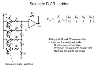
Problem-Solving StrategyApplying Thevenin’s Theorem • Step 1: Remove the load and find the voltage across the open-circuit terminals, Voc. • Step 2: Determine the Thevenin’s equivalent resistance RTh of the network at the open terminals with the load removed. • (a) If the circuit contains only independent sources • Independent sources are made zero by replacing the voltage sources with short circuits and the current sources with open circuits. RTh is then found by computing the resistance of the purely resistive network at the open terminals. • (b) If the circuit contains only dependent sources • Since there is no energy source, the Voc is zero in this case. • Thevenin equivalent circuit is simply RTh. • An independent voltage (or current) source is applied at the open terminals and the corresponding current (or voltage) at these terminals is measured. The voltage/current ratio at the terminals is the Thevenin’s equivalent resistance RTh.
(c) If circuit contains both independent and dependent sources, • the open-circuit terminals are shorted and the short-circuit current Isc between these terminals is determined. Then, RTh = Voc / Isc . • Step 3: If the load is now connected to the Thevenin’s equivalent circuit, consisting of Voc in series with RTh, the desired solution can be obtained. • The problem-solving strategy for Norton’s Theorem is essentially the same, with the exception that we are dealing with the short circuit current instead of the open-circuit voltage.