Download
1 / 11
110 likes | 130 Vues
On a battle field the life of the soldier is more important than a million dollar equipment. Most the equipments used in combat are designed by keeping this in mind. When tank designers come up with a tank with better armor, ammunition designers come up with much better solution to destroy the tank. To tackle these tank designers increased the weight which further makes the tank a sitting duck to the enemy fire. The only solution to this problem is to reduce the weight by reducing the armor, but this will put the soldiers in trouble. So the better solution will be removing both the soldiers and armor from the tank. Thus the concept of remote controlled main battle tank arises and its operational requirements and issues are discussed here.

E N D
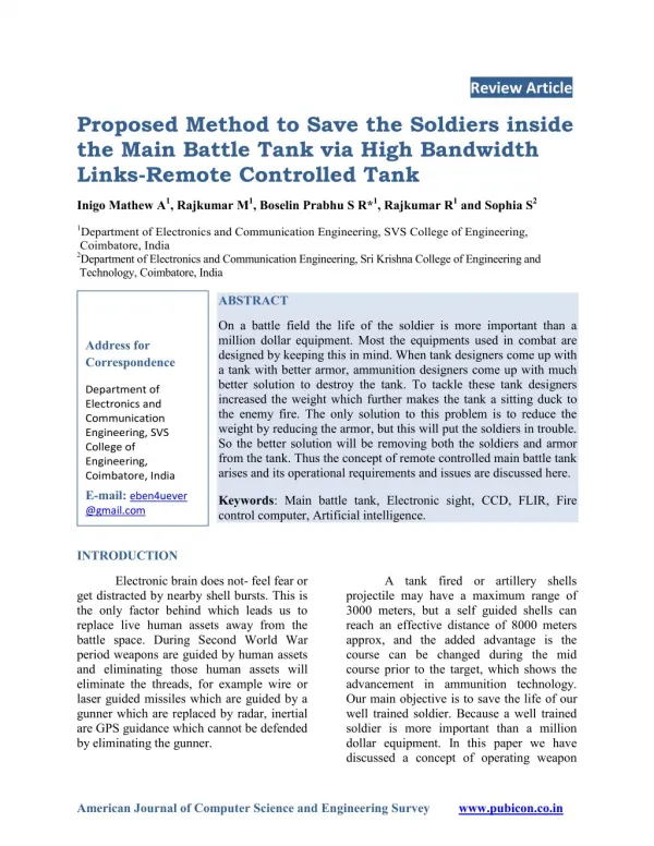
Review Article Proposed Method to Save the Soldiers inside the Main Battle Tank via High Bandwidth Links-Remote Controlled Tank Inigo Mathew A1, Rajkumar M1, Boselin Prabhu S R*1, Rajkumar R1 and Sophia S2 1Department of Electronics and Communication Engineering, SVS College of Engineering, Coimbatore, India 2Department of Electronics and Communication Engineering, Sri Krishna College of Engineering and Technology, Coimbatore, India ABSTRACT On a battle field the life of the soldier is more important than a million dollar equipment. Most the equipments used in combat are designed by keeping this in mind. When tank designers come up with a tank with better armor, ammunition designers come up with much better solution to destroy the tank. To tackle these tank designers increased the weight which further makes the tank a sitting duck to the enemy fire. The only solution to this problem is to reduce the weight by reducing the armor, but this will put the soldiers in trouble. So the better solution will be removing both the soldiers and armor from the tank. Thus the concept of remote controlled main battle tank arises and its operational requirements and issues are discussed here. Address for Correspondence Department of Electronics and Communication Engineering, SVS College of Engineering, Coimbatore, India E-mail: eben4uever @gmail.com Keywords: Main battle tank, Electronic sight, CCD, FLIR, Fire control computer, Artificial intelligence. INTRODUCTION Electronic brain does not- feel fear or get distracted by nearby shell bursts. This is the only factor behind which leads us to replace live human assets away from the battle space. During Second World War period weapons are guided by human assets and eliminating those human assets will eliminate the threads, for example wire or laser guided missiles which are guided by a gunner which are replaced by radar, inertial are GPS guidance which cannot be defended by eliminating the gunner. A tank fired or artillery shells projectile may have a maximum range of 3000 meters, but a self guided shells can reach an effective distance of 8000 meters approx, and the added advantage is the course can be changed during the mid course prior to the target, which shows the advancement in ammunition technology. Our main objective is to save the life of our well trained soldier. Because a well trained soldier is more important than a million dollar equipment. In this paper we have discussed a concept of operating weapon American Journal of Computer Science and Engineering Surveywww.pubicon.co.in
Prabhu S R et al____________________________________________ ISSN 2349 –7238 systems like main battle tanks (MBT), artillery guns remotely to improve the survivability and lethality. But we have discussed operating a MBT as our prime objective Why remote weapon station? Conventional turret of any MBT requires large area over the chassis which also weights more than two tons9. The main reason for such weight of the turret is it has to accommodate two operators and it has to be armored with a thick one inch steal which puts some added weight. Because from the beginning of tank design protection of soldiers life has given more priority than the platform survivability9. The turret is the most common point of attack, because it’s the weakest point compared to any point on the MBT. To accommodate a heavy turret vehicle with wider chassis is required which will increases the chance of detection and make it more vulnerable to enemy fire1. So the best solution in my point of view is to remove the soldiers from the turret and place them far away from the battle space, ie., take control of the tank remotely. Advantages of remote turret Lighter weight- which helps reduce total station weight by 50% and improves platform stability by placing vehicles center of gravity centered and lowered. Ammunition capacity- soldier will provides extra space to store ammunitions. Profile-reduced size will reduce the chance of detection and can easily suppress enemy fire. Cost reduction- the safety of solder cost more than the platform and it is not necessary in this concept. Power consumption-reduced needs reduced power to drive the turret. Remote operability- allows us to take control from anywhere by communicating the vehicle, say run by wire. (See fig. 1) THE OVERALL CONCEPT A normal MBT has the following controls. Driver control- used to maneuver vehicle during combat. Turret control-used for positioning control. Gun control- used to aim at the target. For the above mentioned control around four crew members are required and improper tank design will put their life under thread. No tank design can be said improper, because there was always a healthy competition between the tank designers and the ammunition designers. When designers come with a new tank, ammunition experts come with much better rounds to tear down the tanks9-12. To answer the question of the ammunition designers, tank designers added extra armor to their tanks, increases weight which cause more problem in rapidity and maneuverability. Only solution for this long lasting competition is to remotely operate these tanks, and we don’t need to worry about armor. The block diagram shows how our system functions13-17. (See fig. 2) Driver control One of the best ways to evade from enemy fire was speed. Speed kills, but in the battle field speed saves our life, kill enemy and vice versa. The speed and range of maneuverability is more important for any MBT in any conflict zone. Driver control consist of controls to help the tank move forward, backward, left as well as right. While controlling the tank remotely the delay in signal transmission and reaction time of the hardware in weapon system must be minimized for effective real-time control. eliminating weight AJCSES[3][6][2015] 158-178
Prabhu S R et al____________________________________________ ISSN 2349 –7238 The below figure shows the proven remote controlled vehicle which can be used during combat. (See fig. 3) These sort of remote controlled weapon systems carry effective sensors which provide real-time intelligence. With advanced display virtualization we can make our solders feel they are in the battle, but they are not really. These type of weapons systems carry some array of sensors like Forward Looking Infra Red (FLIR), day and night optics like color CCD, InSb cooled night vision cameras, laser range finders, etc.,7. These sort of sensors helps in effective control of vehicle remotely which helps to attain full potential. Turret control The turret consist of servo motor system which is controlled by the on-board computer (in case of remote control), where the instructions for the computer is sent from the user interface control located far away from the field7. To target a point target selected by the operator, the coordinate data are sent from the user interface consol to the on-board computer, which drives the turret accordingly. Once the target is within the range of the gun, gunner can pull the trigger remotely. To track a moving target, operator first selects a target, the target information are continuously updated to the control consol and the gun position is updated and guided to point on target. The system keeps track on moving target. The servo motors are controlled by digital pins of the on board computer, using PWM to control the movement of servos18-21. The on board computer is the main controller for the positioning of the turret and helps the gunner to take the short7,22. It acts as the onboard master controller for connecting all the individual components and make them work synchronized. Main function is to control the weapon station via remote commands. For a system with servo motors, the controller has to provide PWM signals for at least three motors, for proper positioning of the turret and to aim the main gun4,23-26. Wired communication protocols like CAN would be aided to communicate with other systems with in the remote station. Because it is very important that the reaction time between targeting and firing must be as small as possible. System for such operational capability must requires clock source of 16KHz and above. Gun control The gunner has to keep in mind that other than the force of the projectile many other external factors also influence the projectile. They are drag, gravity, wind direction and even the moisture content of the operational atmosphere2-5. The below figure shows the various force acting on a projectile. (See fig. 4) So the gunner must have some sound knowledge about the aerodynamic factors. But human approach is not appreciable for scenarios like moving targets. In an instance if the light ray (eye sight) bends, ie., if the gunners view is off course because of environmental parameters the gunner will target and shoots at the ghost target. Figure shows how bending light ray, ie., gunners primary view affect the shoot. Other than this the stability of the gun also affects the performance to its worst. For better performance the gun has to be stabilized in two axis. The reason for two axis control is provided in the next figure. Here we go with Fire Control Computer calculates all these parameters affecting projectile and correct accordingly. Probability of first hit not only depends on the projectile course correction. It also depends on the velocity of the vehicle and the tilt with respect to surface. (See fig. 5 & 6) techniques and (FCC). FCC the course AJCSES[3][6][2015] 158-178
Prabhu S R et al____________________________________________ ISSN 2349 –7238 Fire control computer (FCC) FCC is nothing but a processor which considers all the possible factors which affects the hit probability of the projectile and aims the gun accordingly. It consist of some array of sensors which provides the input to the computer to solve complex mathematical relation and the answer is effected as the performance of the weapon system7. Below figure shows how a ballistic fire control computer looks like. In present FCC the data is fed to a system by the soldier who is present inside the weapons system itself. In case if the system or the system operator is eliminated, the whole weapons system can not function and become ineffective6. It also cost the life of the soldier. Artificial automatic thread elimination may provide a solution. But in military particularly under complex weapon system use of AI is limited. (See fig. 7) It acts as the heart of the system. FCC depends on every individual sensor units and each sensor units reports to the FCC at a rate of fifty four times per seconds7. Some of the primary systems which reports to the FCC are as follow. Electronic sights Electronic sights are nothing but CCD cameras which provide input feeds to an LCD display. It had replaced old mechanical sight systems. The function of this sight system is just to display what is looks. It works at infrared wave band of eight to fourteen micrometer. Instead of displaying the video optical feed, it displays the heat signature of the target8. Because well camouflaged targets are more difficult to find in the photograph, but they can’t hide their heat signature easily. It is also known as Target Acquisition and Designation System (TADS) It consist of an array of sensors includes FLIR, CCD, day night optics, and night television system, mostly provides visual information on the target. Sensors FCS depends on various sensor inputs to function, temperature sensor, used to calculate charge (projectile) temperature, barrel temperature, environmental sensor27-29, meteorological sensor, used to calculate wind direction, velocity, humidity sensor, pressure sensor and a compass. In addition to that CANT sensor provide the tilt level of the MBT which are all used to find firing solution. Gun resolver provides the angle to which the barrel had bent which determines the path of the projectile. LASER range finder provides the distance to the target from the tank. Upon all the whole system has to work under a synchronized clock pulse. Tanks velocity may vary with instance and the tilt angle varies depending on the terrain. These variations will affect the performance badly and they have continuously to attain first round hit probability. In other instance the target range may increase or decrease which means they keep on vary and they have to tracked simultaneously to improve efficiency5. All the parameters are reporting to the ballistic fire control computer which displays all the tactical information’s which are displayed to the control consol which is an interactive LCD touch based control which is located compartment. Any shell burst inside the compartment will affect the crew. This block will explain clearly. (See Fig. 8) The solution is to move the crew far away from the battle field. This will save our soldiers. The block diagram clearly explains how remote operation works. (See fig. 9) Based on the displayed information the operator will provide the control signals sensor includes intelligence or to monitored inside the crew AJCSES[3][6][2015] 158-178
Prabhu S R et al____________________________________________ ISSN 2349 –7238 remotely. These signals are transmitted remotely to the main battle tank. Fire control computer located within the battle tank receives the control information and apply those to the respective ports of the computer which drives the tank, eliminating the risk of the solders. CONCLUSION terrains. Only problem we found will be the communication link. The link must have high bandwidth which can support real time transmission of audio, video, command signals to the base station. Reduced size will also helps in easy transport via airlift and reduced deployment time. The hardware used in the weapon station and control centers must have to work with real time schedules and with less delay. The processors must have the ability to multitask several events simultaneously and with better performance results. In future the same will be implemented in hardware and real time issues will be resolved. Remote controlled weapons will be cheaper and it will save the life of the precious soldier. Because the life of the soldier is more important than a million dollar platform. Due to its reduced size the stealthiest platform can be obtained. Reduction in weight will helps to make the platform to maneuver with ease in tough REFERENCES 8.Hendrik Rothea, Markus Graswalda, and Rainer Breiterb “Thermal weapon sights with integrated fire control computers: algorithms and experiences” 9.Stanley C. Crist” The M1A2 Abrams:The Last Main Battle Tank?” 10. http://www.memsnet.org/mems/what-is.html. 11. Thiago Teixeir, Gershon Dublon, “A survey of human-sensing: methods for detecting presence, count, location, track, and identity”, ACM Computing Surveys, Vol. V, No. N, 20YY, Pages 1-77. 12. Michael Winkler, Klaus-Dieter Tuchs, Kester Hughes, and Graeme Barclay. “Theoretical and practical aspects of military wireless sensor networks”, communications and Information Technology, pp. 37-45. 13.K. Akkaya and M. Younis, “A survey on routing protocols for wire-less sensor networks”, Ad-hoc Netw., no. 3, pp. 325–249, 2005. 14.Al-Karaki and Kamal, “Routing techniques in wireless sensor networks: a survey”, IEEE Wirel. Commun., vol. 11, iss.6, pp. 6–28, 2004. 15. Niculescu, “Communication paradigms for sensor networks”, IEEE Commun. Mag., vol. 43, iss. 3, pp. 116–122. 1.“electro optic systems announces new weapon systems and collaboration with ST kinetic on new weapons station maintenance center” http://www.eos-asu.com 2.Vladimir CECH, Ludek JEDLICKA, Jiri JEVICKY “Problem of the reference height of the projectile trajectory as a reduced meteo- ballistic weighting factor” 3.“TANK FIRE CONTROL STUDY, EVALUATION ALTERNATIVE SYSTEMS OF TANK STABILIZATION”, ordnance project tt2- 693, fire control project 429. 4.Pawat Chusilp, Weerawut Charubhun, and Artit Ridluan “Developing Firing Table Software for Artillery Projectiles using Iterative Search and 6-DOF Trajectory Model” 5. “digital ballistic computer for a fire guidance system”, US Patent NO: 4,568,823. 6.Sevsay Aytar Ortac, Umut Durak, Umit Kutluay, Koray Kucuk, Maj. CanCandan” NABK BASED NEXT GENERATION BALLISTIC TABLE TOOLKIT “ 7.Imran Jattala, Junaid Farooqi, Shakeel Durrani, Obaid Bin Zakria, Shoab A. Khan “Ballistic Fire Control Computer (FCC) For Main Battle Tank (MBT)” SYSTEMS OF SOME Journal of Tele- AJCSES[3][6][2015] 158-178
Prabhu S R et al____________________________________________ ISSN 2349 –7238 16. Bhattacharya, Kim, Prabh, and Abdelzaher, “Energy conserving data placement and asynchronous multicast in wireless sensor networks”, Proceedings of the International Conference on Mobile Systems, Applications, and Services (MobiSys), May 2003. 17.Blum, Nagaraddi, Wood, Abdelzaher, Son, and Stankovic, “An entity maintenance and connection service for sensor networks”, First Intl. Conference Applications, and Services (MobiSys), May 2003. 18.Boselin Prabhu, SR & Sophia, S, 2012, ‘A research on decentralized algorithms for dense networks’, International Journal of Computer Applications, vol. 57, no. 20, pp. 35-40. 19.Boselin Prabhu, SR & Sophia, S, 2013, ‘Mobility assisted dynamic routing for mobile wireless sensor networks’, International Journal of Advanced Information Technology, vol. 3, no. 3, pp. 9-19. 20.Boselin Prabhu, SR & Sophia, S, 2013, ‘A review of energy algorithm for connecting wireless sensor network fields’, International Journal of Engineering Research and Technology, vol. 2, no. 4, pp. 477-481. 21.Boselin Prabhu, SR & Sophia, S, 2013, ‘Variable power energy efficient clustering for wireless sensor networks’, Australian Journal of Basic and Applied Sciences, vol. 7, no. 7, pp. 423-434. 22.Boselin Prabhu, SR & Sophia, S, 2013, ‘Capacity based clustering model for dense wireless sensor networks’, International Journal of Computer Science and Business Informatics, vol. 5, no. 1, pp. 1-10. 23.Boselin Prabhu, SR & Sophia, S, 2013, ‘Hierarchical distributed clustering algorithm for energy efficient wireless sensor networks’, International Journal Information Technology, vol. 1, no. 12, pp. 45-55. 24.Boselin Prabhu, SR & Sophia, S, 2013, ‘Real- world applications of distributed clustering mechanism in dense networks’, International Computing Communications and Networking, vol. 2, no. 4, pp. 99-105. 25. Boselin Prabhu, SR & Sophia, S, 2013, ‘An integrated distributed clustering algorithm for dense WSNs’, International Journal of Computer Science and Business Informatics, vol. 8, no. 1, pp. 1-12. 26.Boselin Prabhu, SR, Inigo Mathew,A, & Sophia, S, 2014, ‘Modern cluster integration of advanced weapon system and wireless sensor based combat system’, Scholars Journal of Engineering and Technology, vol. 2, no. 6A, pp. 786-794. 27.Chen, Jamieson, Balakrishnan, and R Morris, “Span: an energy-efficient coordination algorithm for topology maintenance in ad hoc wireless networks”, 6th ACM MOBICOM Conference, 2001 28.Arras, Mozos, and Burgard. "Using boosted features for the detection of people in 2d range data”, In Proc. of the int. conf. on robotics & automation, 2002. 29.Boselin Prabhu, SR, Inigo Mathew,A, & Sophia, S, 2014 “A Review of Efficient Information Delivery and Clustering for Drip Irrigation Management using WSN”. of Research in wireless Journal sensor on Mobile Systems, of clustering sensor wireless efficient clustering AJCSES[3][6][2015] 158-178
Prabhu S R et al____________________________________________ ISSN 2349 –7238 Figure 1. Conventional manned tank turret (credit: www.eos-aus.com) Figure 2. Block diagram of overall concept AJCSES[3][6][2015] 158-178
Prabhu S R et al____________________________________________ ISSN 2349 –7238 Figure 3. Remote controlled weapon station Figure 4. Various factors affecting the flight path of the projectile AJCSES[3][6][2015] 158-178
Prabhu S R et al____________________________________________ ISSN 2349 –7238 Figure 5. Bending of light ray affects hit probability Figure 6. Effect of improper gun stabilization AJCSES[3][6][2015] 158-178
Prabhu S R et al____________________________________________ ISSN 2349 –7238 Figure 7. Ballistic fire control computer of MBT Figure 8. Block diagram of existing FCC AJCSES[3][6][2015] 158-178
Prabhu S R et al____________________________________________ ISSN 2349 –7238 Figure 9. Block diagram of remote control of MBT AJCSES[3][6][2015] 158-178