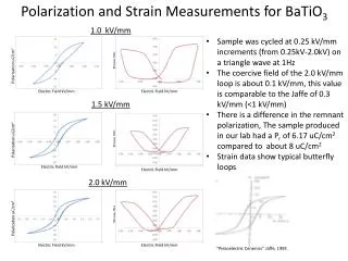
Strain Measurements
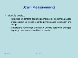
Strain Measurements. Module goals… Introduce students to operating principles behind strain gauges Discuss practical issues regarding strain gauge installation and usage. Understand how bridge circuits are used to determine changes in gauge resistance --- and hence, strain.

Strain Measurements
E N D
Presentation Transcript
Strain Measurements • Module goals… • Introduce students to operating principles behind strain gauges • Discuss practical issues regarding strain gauge installation and usage. • Understand how bridge circuits are used to determine changes in gauge resistance --- and hence, strain. Prof. Sailor
Experimental Stress Analysis • Reasons for Experimental Stress Analysis • Material characterization • Failure analysis • Residual or assembly stress measurement • Acceptance testing of parts prior to delivery or use • Some Techniques • Photoelasticity • Non-contact holographic interferometry • Electrical Resistance Strain Gauges Prof. Sailor
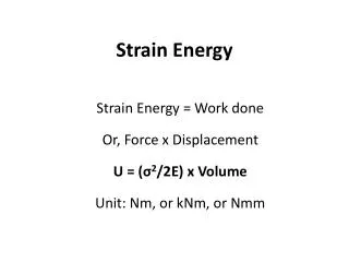
Stress vs. Strain • Strain (e) is a measure of displacement usually in terms of micro-strain such as micro-inches of elongation for each inch of specimen length. • Stress (s) is a measure of loading in terms of load per unit cross-sectional area • Stress and strain are related by a material property known as the Young’s modulus (or modulus of elasticity) E. Prof. Sailor
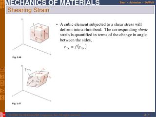
Strain Defined • Strain is defined as relative elongation in a particular direction ea= dL/L (axial strain) et= dD/D (transverse strain) m = et / ea (Poisson’s ratio) T L D T Prof. Sailor
T T Strain gauges • Theelectrical resistance of a conductor changes when it is subjected to a mechanical deformation T Rbefore < Rafter T Prof. Sailor
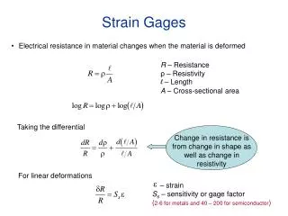
Resistance = f(A…) • Electrical Resistance (R) is a function of… r the resistivity of the material (Ohms*m) L the length of the conductor (m) A the cross-sectional area of the conductor (m2) • R= r* L/A • Note R increases with • Increased material resistivity • Increased length of conductor (wire) • Decreased cross-sectional area (or diameter) • Increased temperatures (can bias results if not accounted for) Prof. Sailor
Deriving the Gauge Factor (GF) • Since L and A both change as a wire is stretched it is reasonable to think that we can rewrite the equation R= r* L/A to relate strain to changes in resistance. • Start with the differential: dR = d r* (L/A ) + r*d(L/A) expanding with the chain rule again one gets: dR = d r* (L/A ) + r/A*d(L)+ r*L*(-1/A2)*d(A) • Divide left side by R and right side by equivalent (r* L/A ) to get: Prof. Sailor
~ 0 for many materials! …substituting into the equation Noting the definition of Poisson’s ratio… Hence, we define the Gauge Factor GF as: Prof. Sailor
Using Gauge Factors with Strain Gauges So, the axial strain is given by … In most applications DR and e are very small and so we use sensitive circuitry (amplified and filtered bridge circuit) contained within a strain-indicator box to read out directly in units of micro-strain. Obviously this strain-indicator will require both R (gauge nominal resistance) and GF (gauge factor) Prof. Sailor
Typical Strain Gauge Prof. Sailor
Steps for Installing Stain Gauges • Clean specimen – degreaser • Chemically prepare gauge area – Wet abrading with M-Prep Conditioner and Neutralizer • Mount gauge and strain relief terminals on tape, align on specimen and apply adhesive • Solder wire connections • Test Prof. Sailor
Beam Loading Example Prof. Sailor
Measuring Strain with a Bridge Circuit • A quarter-bridge circuit is one in which a simple Wheatstone bridge is used and one of the resistors is replaced with a strain guage. • Vo may still be small such that amplification (Amp>1.0) is usually desirable • Note: Vo and Vex are also sometimes labeled as Eo and Ei (or Eex) Non-linear term Prof. Sailor
Current (i) Limitations • In general gauges cannot handle large currents • The current through the gage will be driven by the voltage potential across it. • Note: Text denotes the excitation voltage as Vi. It is also often labeled Ve or Vex. Prof. Sailor
Measuring Strain with a Strain-Indicator • First install a strain gauge • Connect the wires from the strain gauge to the strain indicator. • Apply loading conditions • Read strain from strain indicator • Note that the indicator always displays 4 digits and reads in microstrain! • Thus, 0017 means 17 micro-inches / inch of strain. Prof. Sailor
Strain gauge bridge enhancements • 3-wire configuration addresses lead wire resistance issues • Half-bridge configuration – with a dummy gauge mounted transversely addresses gauge sensitivity to surface temperature • Half bridge – amplification through use of dual gauges Prof. Sailor
Theoretical Determination of Strain in a Loaded Cantilever Beam • You must either know the load P or the displacement (v) • Determine displacement (v) at x=a • Knowing beam dimensions and material (and hence EI) estimate the load P • Calculate stress at location of gauge • Calculate e from s=eE Prof. Sailor
Strain Gauge Vibration Experiment Notes:Cantilever Beam Damping When the cantilever beam is “plucked” it will respond as a damped 2nd order system. The amplitude of vibration has the general form: Where the damped frequency (what you measure) is related to the natural frequency (wn) by: The damping ratio (zeta) can be determined by plotting the natural log of the amplitude/magnitude (M) vs time: So, the slope of the plot of ln(M) vs. t is (– zwn) Prof. Sailor
Additional Considerations for natural frequency of “plucked” beams • Note: Unless otherwise indicated, natural frequencies are expressed in terms of radians/sec. • The natural frequency of a uniform beam is given by: • E is the modulus of elasticity, I is the moment of intertia about the centroid of the beam cross-section (bh3/12), m’ is the mass per unit length of the beam (ie kg/m), and L is the cantilevered beam length • If the beam is not uniform… • A mass at the end can be represented as an effective change in beam mass per unit length • A hole in the end can be accounted for in a similar fashion… Prof. Sailor