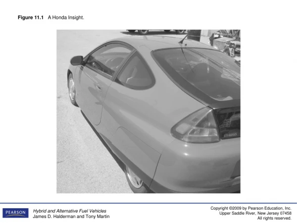
Figure 11.1 A Honda Insight.
320 likes | 915 Vues
Figure 11.1 A Honda Insight. Figure 11.2 The i-VTEC on this Honda ICE is used to keep the valves closed on three of the cylinders to increase the amount of energy that can be recovered during deceleration.

Figure 11.1 A Honda Insight.
E N D
Presentation Transcript
Figure 11.2 The i-VTEC on this Honda ICE is used to keep the valves closed on three of the cylinders to increase the amount of energy that can be recovered during deceleration.
Figure 11.3 The Honda Civic hybrid engine showing the ignition and fuel system components, as well as the valve train and related components.
Figure 11.4 The three modes of operation of the 2006 Civic VTEC system.
Figure 11.6 The modes of operation of the 2006 Civic hybrid.
Figure 11.8 Under most conditions, the IMA motor is used to start the ICE.
Figure 11.9 During acceleration, the battery module provides electrical energy to the IMA motor to help accelerate the vehicle.
Figure 11.10 During deceleration, the IMA converts kinetic energy into electrical energy for recharging the HV battery pack.
Figure 11.11 Instrument display on a Civic hybrid, which shows the auto stop light.
Figure 11.12A The Honda Civic CVT uses a metal drive chain that operates between two cones called a variator. These two cones have a very smooth surface and can be damaged if dirt gets into one of the units.
Figure 11.12B The Honda Civic hybrid CVT transaxle uses a start clutch rather than a torque converter. Because the torque converter, which normally drives a pump to supply hydraulic fluid to the components is not used, the Honda Civic CVT unit uses a chain-driven pump driven by the input shaft.
Figure 11.13 The upstream oxygen sensor is a Lean air–fuel ratio (LAF) sensor on this Honda Accord V-6, whereas the downstream is a conventional zirconia four-wire heated oxygen sensor.
Figure 11.14 The view of the battery pack and the electronic assemblies after removing the rear seat and the steel panel.
Figure 11.15 One six-cell segment of the battery module. The protective plastic covering has been removed. The thin strip taped alongside the batteries is a temperature sensor used by the battery condition monitor to help determine charging and discharging rate based on the temperature of the batteries. While this sensor cannot detect a failure in any one battery, it is capable of detecting a fault in a single strip of batteries.
Figure 11.16 The battery, as well as the electronics, are cooled through this vent on a Honda Civic hybrid.Blocking the airflow through this vent could cause serious damage to the hybrid system and would likely cause the settingof a diagnostic trouble code.
Figure 11.17 Cooling airflow through the intelligent power unit (IPU) of a 2004 Civic hybrid.
Figure 11.18 The heat sink can be seen through the opening where cabin air is drawn through the unit by a fan.
Figure 11.19 The entire Honda Insight hybrid IPU assembly is shown removed and placed on the floor.
Figure 11.21 The conventional 12-volt battery is located under the hood on Honda hybrid vehicles.
Figure 11.22 A cutaway of a Honda electric power steering assembly.
Figure 11.23 The spark plugs used in the Honda Insight are indexed and labeled with a letter on the top.
Figure 11.24A After removing the back seat, remove the access panel to reach the shut-off switch for the high-voltage system
Figure 11.24B Remove the red retainer and flip the switch to the off position. Reinstall the red retainer to prevent the switch from accidentally being moved to the on position.
Figure 11.25A For best results when diagnosing a Honda hybrid electric vehicle, use the factory scan tool.
Figure 11.25B A screen shot of Honda scan data as displayed on a laptop computer.
Figure 11.26 The dipstick from Honda hybrid CVT transaxle. Always clean around the dipstick before removing to prevent the possibility of dirt getting into and contaminating the fluid and causing serious transaxle damage.