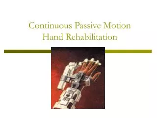
Continuous Passive Motion Hand Rehabilitation
190 likes | 844 Vues
Continuous Passive Motion Hand Rehabilitation. Design Team. Project Sponsors: Bert Lariscy, Vanderbilt University EE graduate Crystal Bates, Occupational Therapist Jim Lassiter, MCN Chief Occupational Therapist Group Members: Jonathan Webb ME Matthew Byrne ME

Continuous Passive Motion Hand Rehabilitation
E N D
Presentation Transcript
Design Team Project Sponsors: • Bert Lariscy, Vanderbilt University EE graduate • Crystal Bates, Occupational Therapist • Jim Lassiter, MCN Chief Occupational Therapist Group Members: • Jonathan Webb ME • Matthew Byrne ME • Jennifer Hornberger BME • Aaron Hadley BME
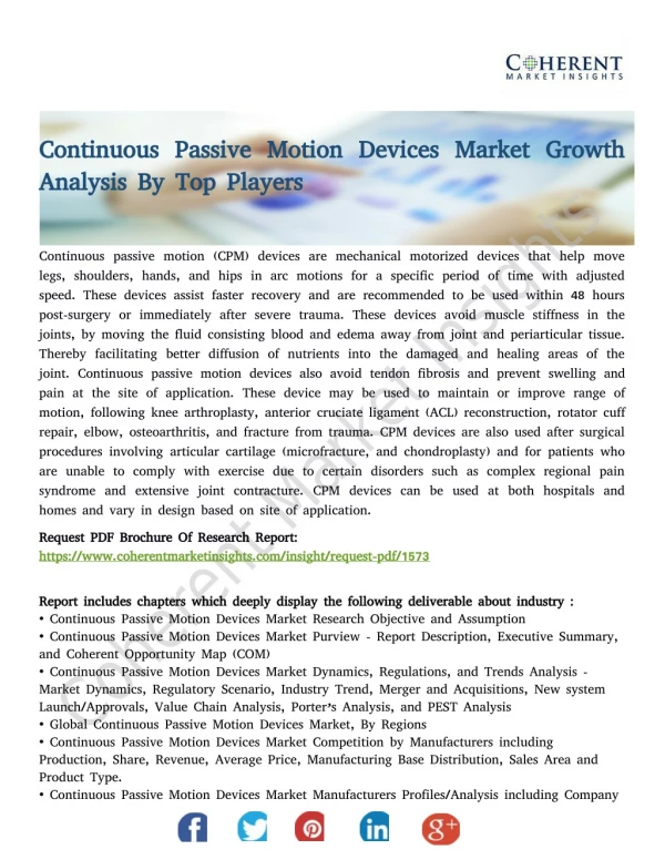
CPM Devices • Continuous Passive Motion is a method of rehabilitation following injury or surgery. • Its main aim is to increase movement of the joints while preventing overextension or further damage and to prevent the buildup of scar tissue.
CPM Market Injuries • Typical surgeries where CPM is needed post operatively: • ankylosis of joints • dislocation of fingers and wrist • sprain and strain of wrist joints • tissue replacement at hand joints
Design Problem • Problems with current CPM device: • fingers not allowed independent motion • thumb not a part of the system • heavy and bulky • complex, difficult to set up and use
Design Goals • It is necessary to make a completely new design that will incorporate independent finger motion, so as to allow for greater customization of rehabilitation. • It must also be lightweight and portable, so that a patient can treat themselves at home. • If possible, the thumb should be incorporated into the design in at least one dimension of movement.
Design Goals Comparison Chart
Design Goals • Following the evaluation of the comparison chart, the following ranking of design objectives was obtained. • The following parameters are not necessary, but desirable in the final design. • Clearly, the portability aspect of the device is the most important to meet patient needs.
Magnetic Field Technique • Magnetic fields can control joints of individual fingers. • By adjusting the strength of the magnet field, the speed of finger movement can be controlled. • The use of magnetic fields will keep the device lightweight and adjustable as only a power source and electric wiring will be needed. • The motion of the fields must be tested to find the extend to which the magnets can be controlled and how much current is needed
Solenoid Experiment Wire is wrapped around a rod, connected to a base through a hinge, and a current is passed through the wire to create a magnetic field. The induced magnetic field is attracted to the base magnet and should allow for control of the rod, resisted by a spring. Results • The magnetic field induced by 12 Volts did not move the wooden rod. • The magnetic field was not strong enough to hold a small screw to the rod. • Size restrictions of fingers will limit the N (loops/meter) value of the solenoid equation. • Currently, alternative types of solenoids are being researched to find if a sufficient magnetic field can be developed from a small loop of coils. Solenoid Equation B = μ*N*I Where μ=4π*10^-7
Mechanical Tension • A series of small pulleys and strings will be used to move the fingers. • These strings would be placed on the palm and back of the hand. • Each finger and even each joint could be moved independently. • A computer would control the length of the strings to set the desired position and allow for tension response.
ME Department’s Artificial Hand • The ME Department’s artificial hand uses similar tendon-like cables. • Tension returns the finger to an extended position. • The “tendons” are inside the finger, but for our CPM model the strings would have to be outside the body.
SMAs (Shape Memory Alloys) • NiTinol (Nickel-Titanium alloy) and other popular SMAs are being currently used in many fields and research is still being conducted to discover their full potential. • Would allow for a simple, lightweight design, and would form precisely with hand. • Unfortunately, would be difficult to deform and reform many times over and maintain precision. Also, the temperature required to activate it maybe unreasonable.
Inflation • Initial inflation of the air/fluid-filled bladder adjustable to fit all hand sizes. • Each finger attached to one of five individual compartments which can be inflated and deflated at different rates to allow for different range of motion in each finger. • Rate of inflation controlled through strain gauges and pressure sensors. • Problems • How to provide feedback so device will stop if there is too much resistance
Future Directions • Continue testing of ideas • Decide exactly which ideas to incorporate in design • Create prototype