Inelastic Scattering Beamline Update
Inelastic Scattering Beamline Update. Yong Cai Inelastic X-ray Scattering Group Experimental Facilities Division, NSLS-II Experimental Facilities Advisory Committee Meeting April 23-24, 2009. Outline. Beamline Overview Technical Requirements Progress Since Last EFAC Conceptual Design

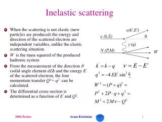
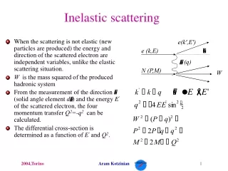
Inelastic Scattering Beamline Update
E N D
Presentation Transcript
Inelastic Scattering Beamline Update Yong Cai Inelastic X-ray Scattering GroupExperimental Facilities Division, NSLS-II Experimental Facilities Advisory Committee Meeting April 23-24, 2009
Outline Beamline Overview Technical Requirements Progress Since Last EFAC Conceptual Design Insertion Device Optimization Performance Issues Budget and Schedule Outlook (Near Term)
Beamline Overview • IXS experiments at extremely high resolution of 0.1 meV at ~10 keV Akey goal of NSLS-II Bridging partially the dynamical gap between existing high and low frequency probes • Proposal from BAT: two instruments based on the new optical design • Ultrahigh (0.1 meV) resolution • High resolution (0.5-1 meV) • Improved resolution tails E ~ 9 keV • Well matched to NSLS-II undulator performance • Count rate issues (see later) • Scientific areas • Collective dynamics in liquids, glassy and biomolecular systems • Phonons in single crystals, surfaces, thin films, high pressure systems, small samples
Technical Requirements • Incident flux at sample > 109 photons/sec/0.1meV State-of-the-art Instruments: ~109 photons/sec/1meV • Energy resolution: 0.1 meV and 0.5~1 meV Sharp resolution tail offered by the new scheme • Q range / resolution: Disordered/confined systems: 0.02 ~ 10 nm-1 / 0.01 nm-1 Soft matter: 0.1 ~ 40 nm-1 / 0.1 nm-1 Hard matter 0.1 ~ 80 nm-1 / 0.1 nm-1 or lower Parallel data collection • Focus: Vertical focus < 5 µm For high pressure, 1 µm (V) x 3 µm (H) desirable • Sample environments Compatible with high pressure, low-T (4K), high-T (1000K), and single crystals
Progress Since Last EFAC (May 5-7, 2008) Major progress achieved in 0.1 meV optics R&D program Buildup of infrastructure (dedicated R&D beamline and optics test end station at NSLS, crystal fabrication lab) Proof of principle experiment completed Greatly improved understanding of the technical requirements and challenges of the new optics schemes, and other possible alternatives Refined beamline conceptual design More realistic insertion device plan First BAT meeting addressing issues and concerns raised by EFAC Near-term milestones on 0.1 meV optics R&D Response to EFAC comments Action items on beamline design First BAT meeting (Dec 5, 2008)
Current Conceptual Design • Insertion device: an IVU22-6m at a high-β long straight section as the new baseline device • Generic front-end for long straight section with beam defining X-Y slits • Be/Diamond CRL’s in front-end to collimate beam (to ≤ 10 µrad) being evaluated • Cryogenic cooled DCM, FEA analysis being revisited for IVU22-6m • CDDW high-resolution mono + channel cut for 1 – 0.1 meV resolution switching • KB focusing mirrors to focus beam to < 5 x 5 µm2,divergence ≤ 0.1 mrad to ensure q resolution • ML mirror(s) to collect 5 x 5 mrad2 scattered fanhorizontal to < 0.1 mrad (q resolution)vertical to < 0.1 mrad (analyzer acceptance)or other alternative schemes • 10 m arm and Area detector CRL 30m Single mirror possibilities
Possible Combination of End Stations DCM Beamline to occupy a high-β long straight section HRM(CDDW + CC) Combine two end stations in one hutch KB + PP FOE • 1.0 meV Arm • CDDW Analyzers (1.0 meV) • 0.1nm-1 q resolution • 0.1~80nm-1 q range (~120°) • ½ wave phase plate to rotate polarization near 90° • (mature scope) • 0.1 meV Arm • CDDW Analyzers (0.1 meV) • 0.01 nm-1 q resolution • 0.1~40 nm-1 q range
Insertion Device Optimization • Flux at sample > 109 photons/s/0.1meV Flux at source > 1015 photons/sec/0.1%bw(assuming 10% overall beamline optics efficiency) • Optimization to maximize flux at 9.1 keV: magnet period vs length vs minimum gap Fundamental Photon Energy vs Gapfor Different IVU Periods IVU Lengths ~Satisfying “Stay Clear” Constraint in High-Beta Straight Section IXS requirement @ 5th Harmonic Calculations by O. Chubar IVU parameters by T. Tanabe βy0 value suggested by J. Bengstsson βy0 = 3.4 m
Key Points on Insertion Device The baseline IVU20-3m cannot be used on a high-β straight due to “stay-clear” constraint The high-β straight offers lower heat load on optics and smaller beam cross section throughout the beamline An IVU22-6m device based on current “warm” NEOMAX magnet NdFeB with Br = 1.12T provides the best possible performance with the current lattice design. Maximum spectral flux = 1.6x10¹⁵photons/sec/0.1%bw @ 9.1 keV, aperture 100μrad (H) x 50 μrad (V) Important accelerator-related issues (e.g., tune shift compensation) need to be addressed Further optimization possible with cold devices and/or extended long straights Maximal Spectral Flux through 100 μrad (H) x 50 μrad (V) Aperture E-Beam Current: 0.5 A High-β Straight Section By O. Chubar 9.1keV @ 5th Harmonic
Partially-Coherent Wavefront Propagation Simulations for IXS: Beam Collimation by 1D CRL By O. Tchoubar Spectral Flux through 100 μrad (H) x 50 μrad (V) Ap. 1D CRL (Be, parab., Fy~15 m @ 9.1 keV, rmin~250 μm, dy = 1 mm, 2 lenses) U22-6m Harm. 5 #3 #1 #4 #2 #5 10 m 20 m 20 m 60 m (from CRL) Vertical Cuts (x=0) Intensity Distributions at Different Longitudinal Positionsat Photon Energy near H5 Peak (9.114 keV) #1: Before CRLF ≈ 1.5x10¹⁵ Ph/s/0.1%bw #2: Just After CRLF ≈ 1.37x10¹⁵ Ph/s/0.1%bw #3: At 10 m After CRL #4: At 20 m After CRL #5: At 60 m After CRL (vertical waist) Horizontal Cuts (y=0)
Estimated U22 Total Emitted and Absorbed (by CRL) Power Density Distributions By O. Chubar Total Emitted (integrated over all Photon Energies) P ~ 10 kW CRL Integral Absorbed Power Density inside CRL Work in progress … Absorbed Power Densityvs Vertical Position at x = 0 CRL Transmission at 9.1 keV
Shadow Ray Tracing (in progress…) • Initial tracing by Oxford-Danfysik: • New tracing, to be performed, to include: • Insertion device IVU22-6m • Be CRL + filter, or collimating mirror • FEA analysis of Be CRL and DCM • Tracing thru CDDW optics CDDW optics in Shadow
Given the same q resolution, I/I0 is proportional to analyzer solid angle and sample absorption length: Count Rate Estimates (9.1 vs 21.7 keV) State-of-the-art experiments operate with count rate @ ~ 1cnts/sec (Data courtesy of M. Krisch) H. Sinn, J. Phys. Cond. Mat. 13, 7525 (2001)
Count Rate Estimates (continued) • Sample volume (thickness) not optimized for higher energies by up to a factor of 25! • Not always possible to go with the absorption length (e.g., biological samples) • High-pressure samples limited by pressure vessels • Angular acceptance of backscattering analyzers is resolution limited • Estimate for NSLS-II spectrometer operating at 9.1keV compared to ESRF ID28 Estimated CR = Mea. CR x labs Gain x SA Gain x Int. Gain • Here we assume: • Experiments at 9.1keV can be carried out with sample thickness of one absorption length • New optical scheme delivers flux of 1x10¹⁰ ph/sec at 1meV resolution • New analyzer scheme is as efficient as state-of-the-art backscattering analyzers
Cost Baseline ($ x 1000) WBS Dictionary:All activities related to design, construction, and commissioning (without beam) of an insertion device beamline for inelastic x-ray scattering. Includes three enclosures • Major components Include: • Slits: $180K • Beam Monitors: $169K • Fluor. Screens: $106K • KB mirrors (1set): $652K • VFM/VCM (1set): $301K Cost estimate currently under revision! Includes the 0.1meV HRM and the spectrometer
Schedule Summary • Now~2011: Actively pursue 0.1meV resolution R&D and design beamline based on 1meV prototype • 2011~2013: Construct beamline based on 1meV resolution but ensure compatibility with 0.1meV resolution, continue R&D to achieve 0.1meV • 2014~2015: Commission 1meV instrument, develop 0.1meV instrument with NSLS-II source • 2016~: realize 0.1meV goal. (no major impact on basic beamline design)
Outlook for the Next 6 Months Continue to work with ASD to re-baseline insertion device (IVU22-6m) Complete FEA heat load analysis on DCM and Be CRL’s Complete Shadow ray tracing including CDDW mono plus channel cut Complete efficiency analysis of analyzer system Carry out more realistic count rate estimates Revise cost estimates Finalize conceptual design