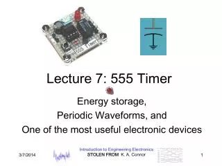

Section 24.4 The 555 Timer
E N D
Presentation Transcript
Rectangular Waves- Reminder: Duty Cycle – ratio of pulse width to cycle time where PW= the pulse width of the circuit input T= the cycle time of the circuit input 2
Rectangular Wave If you repeatedly switch between the battery and the short you are effectively applying a rectangular time pulse to the RC circuit. b) If SW = PW, what is the duty cycle? a) If SW = .5 PW, what is the duty cycle?
Rectangular Wave Response The voltage across the capacitor will behave as below in response to such a wave:
In-Class Activity • For the circuit above, what value of C will allow the capacitor to “fully” charge and “fully” discharge if the square wave has a period of 2ms? • What is the time constant for this circuit?
In-Class Activity • Determine the charging time constant and the discharging time constant in the circuit below:
The 555 Compares the voltage at pin 6 to 2/3 Vcc The 555 Compares the voltage at pin 2 to 1/3 Vcc
Typical Wiring for a 555(astable mode) Notice that the boxed area is just an RC circuit
Current Flow During Capacitor Charging The capacitor charges via RA and RB until vc = 2/3 Vcc
Capacitor Voltage and Output Voltage Vcc 0 Red arrows indicate voltages during charging phases
Current Flow During Capacitor Discharging The capacitor discharges through just RB until vc = 1/3 Vcc
Capacitor Voltage and Output Voltage Vcc 0V Blue arrows indicate voltages during discharging phases
Timing During the charging phase, the capacitor voltage can be written as: During the discharging phase, the capacitor voltage can be written as:
In-Class Activity • How long does it take to:a) charge up from 1/3 Vcc to 2/3 Vcc? • Hint: Calculate time to reach each voltage first then subtract • b) discharge from 2/3 Vcc to 1/3 Vcc
555 Timing • Pulse width – capacitor charging time:PW = (RA + RB)C ln(2) sec • Space width – capacitor discharging time:SW = RB C ln(2) sec • Period = Pulse width + Space widthT = PW + SW = (RA + 2RB)C ln(2) sec • Frequency – 1/Periodf = 1/(RA + 2RB)C ln(2) = 1.443/(RA + 2RB)C Hz
555 Duty Cycle • Duty Cycle = 100 PW/T %or
In-Class Activity • In Multisim, build this 555 circuit, use RA = RB = 1kΩ and C = 1µF. • 555 can be found in Place-Mixed-Timer-LM555CM • What are the following: T, PW, SW, duty cycle, f? • Show them in hand calculations and record what you see on Multisim oscilloscope