RailTech PDR
This document outlines the design and objectives of a high-voltage railgun project developed by a team of engineers. Key components include a linear accelerator utilizing voltage applied to rails, a pneumatic kick-start mechanism for projectile launch, and comprehensive safety features such as voltage sensors and Faraday cage protection. The project also highlights effective communication among team members, division of labor across three main areas: railgun, control system, and user interface, and the use of advanced capacitors and materials to enhance performance and safety.


RailTech PDR
E N D
Presentation Transcript
RailTechPDR Group Members: Mike Oertli Jonathan Karnuth Jason Rancier September 11, 2008
Project Overview • Linear accelerator • Voltage applied to rails • Projectile shorts out rails creating EM field • Pneumatic kick-start • Projectile accelerates forward
Basic Design • Conducting rails mounted to non-conducting surface • Capacitor array • PCB, logic, and UI • Conducting metallic projectile
Objectives • Safety!!! • Adjustable voltage from capacitor bank • User interface • Keypad and LCD • Sensor data • Velocity calculations • Remote/Hands off (Safety!)
Approach • Split into 3 main areas • Railgun • Control system • User interface • Each person focus on one area • Communication and compatibility is key
Power Supply • Brute Force discharge • Basic supply, dumps a lot of current directly on rails • Simple to design, overkill on capacitance • Inefficient, back EMF problems • Recharger Supply • Complex LC timing based on rails • Prone to failure with bad design • Requires more capacitors (if polarized are used) • Much more efficient • Fast recharging
Capacitors • Capacitance: 610,000µF • Voltage: 20VDC • 30VDC surge • ESR: 2.1mΩ max • Type: Electrolytic • Number used: ~20 • Cost: ~ $400
Capacitor Array • Mounted capacitors • Connected by switches controlled by logic based on input voltage from user • Logic will be based on test shots • In enclosed case (Safety) • Other possibilities: • Manual switches • Switch mode power supply • Input inductor between array and rails • Ramps current to rails • Avoid discharging capacitors too fast
Rail types • Cylindrical • Easier to fabricate • Fewer pieces • Stronger using less material • Rectangular • Easier to mount • Better electrical properties, distributed current
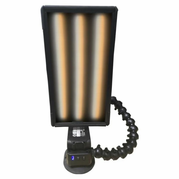
Example of rail Conducting rails
Materials • Rails: Brass • Projectile: Aluminum • Base: Garolite & Teflon • Capacitors: 20x 0.6F 20 v Electrolytic • Microcontroller: MSP430 family - 16 bit • PCB • Power supply • Sensors (EM, voltage) • Keypad and LCD
Brass Rails • Composite: ~70% Copper, ~.07% Lead, ~.05% Iron, Remainder Zinc • Electrical Conductivity: 28% IACS • Electrical Resistance: 6.2µΩ/cm • Friction: Very low with Most metals • Melting Point: 910oC • Inner/Outer Diameter: 0.87”/1” • Cost: $58.68 for 36”
Projectile • Metal: Aluminum • Composite: 2011 • Temper: T3 • Part #: 88615K411 • Melting point: 540oC • Electrical Conductivity: 45% IACS • Electrical Resistivity: 3.8µΩ/cm • Diameter: 7/8” • Length: ~1” • Cost: $17.41/foot
Pneumatic Kick-start • Avoids spot welding projectile • Added kinetic energy • Eliminates static friction coefficients • Compressed Air/CO2 system • Activated by Microcontroller post safety checks
Safety Features • Voltage sensors on rails, cap bank, & source • Kill power if out of expected range • EM Field Sensor • Faraday cage if EM field great enough • Plexiglas casing • Keep user isolated from high voltages and short circuited rails
Block Diagram Capacitor Array Inductor Rails Power Supply Kill Switch Keypad LEDs MSP430xxxx LCD
Microcontroller • MSP430xxxx family • Testing on MSP430F169 • 16-bit for accurate calculation of sensor data • Control safety logic based on sensor values • Disconnect switches from caps to rails • Display values on LCD
Software Engineering • Interface with Matlab • Import sensor data • Statistical analysis • Display results to user as graphs and tables • Maintain records
PCB Elements • Power supply • MSP430 Family • Debug/information LEDs • LCD (3 or 4 rows) • Keypad input • Communication with sensors(A/D)
Sensor • Measure voltage at high sample rate • Used for analysis and safety logic • Implementation: • Voltage transducer • Sample @ 10 MHz + • Response time < 50μs
User Interface • Basic keypad • Input desired voltage to apply to rails • 3 or 4 line LCD on PCB • Output sensor data and statistics • Basic input user interface • If time: • Keyboard input • Computer monitor with GUI • Matlab sensor data analysis
“Real World” Application • Control System for other high voltage applications • Accelerator for fun, military, other scientific research • Capacitor array for high current burst power systems • Sensor to Matlab interface
Realization • Stay under budget by getting donations • Establish primary goals/reasonable functionality • Operate within these • Add incremental levels of difficulty based on time
Plan B • Risk: • Projectile fuses to rails • Discontinuities in the rails and base • Arcing- heat/damage to rails • Unfamiliarity • Sensing systems • Matlab interface • Recovery • Ask for help! • Use heavier duty components • RTFM • Have extra rails and projectiles ready