Aircraft Landing Gear Systems Training Manual
870 likes | 1.3k Vues
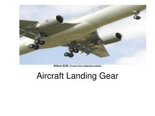
This training manual for maintenance technicians covers landing gear system components, operation, and maintenance procedures. Includes safety warnings and indications. Learn about main and auxiliary landing gear configurations. Updated August 2007.

Aircraft Landing Gear Systems Training Manual
E N D
Presentation Transcript
LANDING GEAR SYSTEMS THIS TRAINING MANUAL HAS BEEN PREPARED FOR MAINTENANCE TECHNICIANS AND DOES NOT SUPERSEEDED INFORMATION CONTAINED IN APPLICABLE AIRCRAFT DOCUMENTS
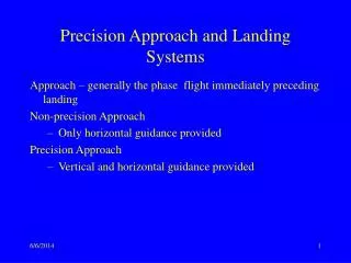
LEARNING OBJECTIVE Will have a knowledge and demonstrate of: Landing gear system components, safety warning indication, system operation and maintenance. Page 2 Aug 2007
LANDING GEAR SYSTEM Page 3 Aug 2007
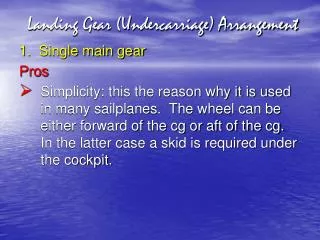
LANDING GEAR SYSTEM • Aircraft Landing Gear, consists: • Main Landing Gear. • Auxiliary Landing Gear. • Where may or may not be retractable.
LANDING GEAR SYSTEM Main Landing Gear forms the principle support of the aircraft on land or water (include any combination of wheels, floats, skis, shock-absorbing, brake, retract mechanism, controls and warnings).
LANDING GEAR SYSTEM Page 6 Aug 2007
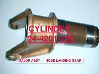
LANDING GEAR SYSTEM Auxiliary Landing Gear, consists of tail or nose wheel; skids; necessary cowling.
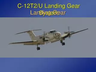
LANDING GEAR SYSTEM Tricycle landing gear retractable are arrangement with the Main Gears and Nose Gear. Main gear consist of two oleo/pneumatic struts with pair of wheels and brakes. Nose gear steerable oleo/pneumatic. Page 8 Aug 2007
LANDING GEAR SYSTEM Some of aircraft have dual wheels on strut and more than two wheels referred to as “bogie”. Retraction and extension by hydraulic with selector lever in the flight compartment. Alternate extension can be mechanically, pneumatic compressor air. Page 9 Aug 2007
LANDING GEAR SYSTEM Shock strut contains hydraulic that support aircraft on the ground and protect structure by absorbing shock load. Consists of two telescopic cylinder (inner and outer). Lower chamber always filled with fluid, the upper chamber contains compressed air.
LANDING GEAR SYSTEM Orifice/metering pin between two chamber provides a passage of fluid during extension retraction.
LANDING GEAR SYSTEM Controlling the rate of fluid flow during compression. Damping or snubbing on some shock strut equipped to reduce the rebound during extension prevent rapidly extension of shock strut. Axle on shock strut to provide for installation of wheels.
Fluid filler and air valve assembly to provide of filling the strut with hydraulic and inflating air.
Packing gland designed to seal sliding also to keep sliding surface free form dirt would result in leaks.
LANDING GEAR SYSTEM Shock struts are equipped with torque arm/link attached to upper and lower cylinders to maintain correct alignment of the wheel. Nose strut provided with upper locating cam attached to upper cylinder and a mating lower locating cam (centering cam), this cam lineup to straight of wheel when strut fully extended; prevent possible structural damage. Page 17 Aug 2007
LANDING GEAR SYSTEM When strut extends contacting slopping area centering contact and slides, so aligns and rotates the nose gear into a straight a head direction. Page 18 Aug 2007
LANDING GEAR SYSTEM Shimmy damper attached on gear struts self-contained hydraulic to prevent wheel fast left-right/flutter (oscillation) during rolling, accomplished by metering of hydraulic fluid through small orifice of two chamber. Page 19 Aug 2007
LANDING GEAR SYSTEM Page 20 Aug 2007
LANDING GEAR SYSTEM • Shimmy Damper (Nose wheel). • Control vibration or shimmy through hydraulic damping and prevent shimmy during take-off roll. • Piston type. • Vane type. • Incorporated in the nose wheel power steering. Page 21 Aug 2007
LANDING GEAR SYSTEM Page 22 Aug 2007
LANDING GEAR SYSTEM Van type located just above nose wheel fork may be mounted either internally or externally. Page 23 Aug 2007
LANDING GEAR SYSTEM Steer damper is hydraulically operated, basically containing rotary van-type (similar to vane-type). Page 24 Aug 2007
LANDING GEAR SYSTEM • Servicing shock strut: • Jacking the aircraft. • Release air valve slowly (ensure the strut compress). • Fill the strut with approved fluid to the level service. • Inflate the strut using nitrogen air pressure. • Tighten the air valve. • Inspect shock strut for leakage and proper extension. Page 25 Aug 2007
LANDING GEAR SYSTEM Page 26 Aug 2007
LANDING GEAR SYSTEM Torque Link-keep the landing gear straight is attached to upper cylinder and lower cylinder of shock strut. Links are hinged while the cylinder can move up and down. Page 27 Aug 2007
LANDING GEAR SYSTEM The strut attached to the structure to enable the strut swing. Drag struts are hinged so the landing gear can be retracted. Page 28 Aug 2007
LANDING GEAR SYSTEM An electric gear retraction, using motor converts electrical energy to rotation. Control by switch, the motor movement be reverse while gear to down. Page 29 Aug 2007
LANDING GEAR SYSTEM Page 30 Aug 2007
LANDING GEAR SYSTEM Page 31 Aug 2007
LANDING GEAR SYSTEM Page 32 Aug 2007
LANDING GEAR SYSTEM Page 33 Aug 2007
LANDING GEAR SYSTEM Page 34 Aug 2007
LANDING GEAR SYSTEM Page 35 Aug 2007
LANDING GEAR SYSTEM Page 36 Aug 2007
LANDING GEAR SYSTEM Page 37 Aug 2007
LANDING GEAR SYSTEM Page 38 Aug 2007
LANDING GEAR SYSTEM Page 39 Aug 2007
LANDING GEAR SYSTEM Landing gear safety devices. Prevent collapse the gear when the aircraft is on the ground. Page 40 Aug 2007
LANDING GEAR SYSTEM Page 41 Aug 2007
LANDING GEAR SYSTEM To provide a visual indication of landing gear position, indicators are installed in flight compartment. A horn and lights comes on when one or more throttles retarded and landing gear is other than down and lock. Page 42 Aug 2007
LANDING GEAR SYSTEM NOSE GEAR NOSE GEAR NOSE GEAR NOSE GEAR LEFT GEAR RIGHT GEAR LEFT GEAR RIGHT GEAR LEFT GEAR RIGHT GEAR LEFT GEAR RIGHT GEAR UP OFF DN L A N D I N G G E A R Page 43 Aug 2007
LANDING GEAR SYSTEM NOSE GEAR NOSE GEAR NOSE GEAR NOSE GEAR LEFT GEAR RIGHT GEAR LEFT GEAR RIGHT GEAR LEFT GEAR RIGHT GEAR LEFT GEAR RIGHT GEAR UP OFF DN L A N D I N G G E A R Page 44 Aug 2007
LANDING GEAR SYSTEM NOSE GEAR NOSE GEAR NOSE GEAR NOSE GEAR NOSE GEAR LEFT GEAR RIGHT GEAR LEFT GEAR RIGHT GEAR LEFT GEAR RIGHT GEAR LEFT GEAR RIGHT GEAR LEFT GEAR RIGHT GEAR LEFT GEAR RIGHT GEAR UP OFF DN L A N D I N G G E A R Page 45 Aug 2007
LANDING GEAR SYSTEM NOSE GEAR NOSE GEAR NOSE GEAR NOSE GEAR NOSE GEAR LEFT GEAR RIGHT GEAR LEFT GEAR RIGHT GEAR LEFT GEAR RIGHT GEAR LEFT GEAR RIGHT GEAR LEFT GEAR RIGHT GEAR UP OFF DN L A N D I N G G E A R Page 46 Aug 2007
LANDING GEAR SYSTEM NOSE GEAR NOSE GEAR NOSE GEAR NOSE GEAR NOSE GEAR NOSE GEAR LEFT GEAR RIGHT GEAR LEFT GEAR RIGHT GEAR LEFT GEAR RIGHT GEAR LEFT GEAR RIGHT GEAR LEFT GEAR RIGHT GEAR LEFT GEAR RIGHT GEAR UP OFF DN L A N D I N G G E A R Page 47 Aug 2007
LANDING GEAR SYSTEM NOSE GEAR NOSE GEAR NOSE GEAR NOSE GEAR NOSE GEAR NOSE GEAR LEFT GEAR RIGHT GEAR LEFT GEAR RIGHT GEAR LEFT GEAR RIGHT GEAR LEFT GEAR RIGHT GEAR LEFT GEAR RIGHT GEAR LEFT GEAR RIGHT GEAR UP OFF DN L A N D I N G G E A R Page 48 Aug 2007
LANDING GEAR SYSTEM Ground Lock. Prevent collapse the gear when the aircraft is on the ground, additional safety devices are installed (ground lock pins) which have red tape REMOVE BEFORE FLIGHT. Page 49 Aug 2007
LANDING GEAR SYSTEM Page 50 Aug 2007