Download
1 / 50
720 likes | 1.79k Vues
Precision Approach and Landing Systems. Approach – generally the phase flight immediately preceding landing Non-precision Approach Only horizontal guidance provided Precision Approach Vertical and horizontal guidance provided. Precision Approach and Landing Systems.

E N D
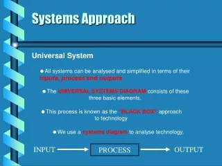
Precision Approach and Landing Systems • Approach – generally the phase flight immediately preceding landing • Non-precision Approach • Only horizontal guidance provided • Precision Approach • Vertical and horizontal guidance provided
Precision Approach and Landing Systems • Precision Approach Categories • Cat I: 200 Ft. ceiling 2600 Ft. visibility • Cat II: 100 Ft. decision height, 1200 Ft. RVR* • *Runway Visual Range • Cat III: • subcat a: 0 Ft. decision height, 700 Ft. RVR • subcat b: 0 Ft. decision height, 150 Ft. RVR • subcat c: 0 Ft. decision height, 0 Ft. RVR
Precision Approach and Landing Systems • Note: The higher the category, the more stringent the requirements for ground and air installations and pilot qualifications • e.g. • extra runway lighting (centreline), approach lighting • redundant transmitters (hot spares) • autoland
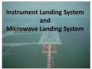
Precision Approach and Landing Systems • Precision Instrument Approach Systems • Instrument Landing System (ILS) • Microwave Landing System (MLS) • Differential GLS (Local and WAAS)
Instrument Landing System (ILS) • ICAO standard approach system • Developed in late 1940’s • Over 110 installed in Canada
Instrument Landing System (ILS) • Components • Localizer - horizontal guidance. • Glide Path (or Glide Slope) - vertical guidance • Marker Beacons - along - track position fixes (obsolete) • DME (sometimes) • Approach Lighting
Instrument Landing System (ILS) • Frequency (Localizer): 108MHz-112 MHz • Even 10ths – gives 40 frequencies • As with VOR, interference from FM broadcast stations can be a problem • Frequency (Glide Path): 329MHz – 335 MHz (paired with localizer frequencies as specified by ICAO) • Note: Receiver automatically selects Glide Path frequency when Localizer frequency is tuned
Localizer • The localizer antenna array is located at some distance (usually about 1000 Ft.) off the stop end of the runway
Localizer • The antenna array radiates two signals each with its own antenna pattern. One pattern is modulated with a 150Hz AM tone, the other with a 90 Hz tone When the aircraft is on the left of the extended runway centreline, the 90Hz tone predominates and when it is on the right, the 150 Hz tone predominates. When the aircraft is on course, the two tones are equal
Glide Path • The Glide Path antenna is usually located about 1000 Ft down the runway from the threshold and 400 Ft. off to the side
Glide Path The signal format is the same as for the localizer but rotated 90. In order to minimize the height of the antenna, the ground is used as a reflecting surface.
Glide Path Note: Because the ground is used in the generation of the Glide Path signal, variations in the ground conductivity and/or level will change the Glide Path angle. One problem is snow, which raises the level of the conducting surface. During snow storms, the clearing of the area in front of the Glide Path antenna has second priority (after crash routes) NOTE: The glide path signal “flares” starting around 2600 Ft from threshold. Also, the structure (deviations) becomes quite large. Thus the Glide Path is not a reliable source of vertical position information for AUTOLAND systems
Markers Part of the ICAO specification for ILS includes a facility called a marker. Markers are almost extinct now, but their original function was to provide an indication of the distance of the aircraft from touchdown.
The OUTER marker (modulated with Morse Code dash dash dash etc.)is located about 4 NM from threshold and indicates the start of the final descent The MIDDLE marker (modulated with dash dot dash dot etc.) is located about 2500 Ft from threshold and indicates the decision point for Cat I approaches The INNER maker (modulated with dot dot dot etc.) is about 1200 Ft from threshold and indicates the decision point for Cat II approaches Markers
Outer Middle Inner Markers Markers all operate at a frequency of 75 MHz. Their radiation patterns are narrow and pointed upwards so that the aircraft receives the signal only when it is directly overhead.
90Hz Filter + + Demodulation Tuning + - 150Hz Filter Guidance ILS Aircraft Installations The aircraft receiver is relatively simple since all it has to do is measure the amplitudes of the 90Hz and 150Hz modulations and provide an error signal: The sum of the modulations is also provided as an integrity check Antenna Flag
ILS Aircraft Installations Antennas: Localizer: Uses the same antenna as the VOR. Either a half-wave dipole or a loop.
ILS Aircraft Installations Dash 8 LOC/VOR Antennas
ILS Aircraft Installations Antennas: Glide Path: Normally the Glide Path antenna is a dual loop mounted inside the radome Radar Antenna Glide Path Antenna
ILS Aircraft Installations Antennas: Glide Path: On Long bodied aircraft the radome is not a good location 3
ILS Aircraft Installations Antennas: Glide Path: On 747’s and other such aircraft, the Glide Path antennas are mounted on the nose gear doors. Another consideration is that, in the radome, the radar antenna may influence the reception from the Glide Path antenna
ILS • Accuracy: • Localizer: • Maximum error defined by ICAO at the point where the average localizer course crosses the runway threshold • Cat I: ±35 Ft. (0.29 for a 6000Ft. Runway) • Cat II: ±25 Ft. (0.20 for a 6000Ft. Runway) • Cat III: ±10 Ft. (0.08 for a 6000Ft. Runway) • Glide Path: • 0.056θ where θ is the Glide Path angle (0.168 for 3 GP angle)
ILS • Irregularities: • The course lines are generated by antenna patterns which can be altered by the presence of reflecting surfaces such as hangars and other aircraft. • Thus the localizer and glide paths are never straight lines but the deviations from nominal (called “structure”) are controlled by the ICAO specification. • The allowable deviations decrease as the threshold is approached 2500 Ft 4 NM
ILS • Integrity: • The ground station includes monitors which will detect out of tolerance conditions and either switch transmitters or turn off the transmission. • The receiver measures the modulations and sets a flag if the sum of the modulations goes below a given threshold
Integrity: • The ground station includes monitors which will detect out of tolerance conditions and either switch transmitters or turn off the transmission. • Response time is 10 seconds for Cat I and 2 seconds for Cat II and III. Thus Cat II and III systems require that the standby transmitter be on at all times (hot spare) • The receiver measures the modulations and sets a flag if the sum of the modulations goes below a given threshold ILS
Future of ILS: • Threats: • FM broadcast stations • Relatively few channels available (40) • Susceptibility to interference • Limited Glide Path angle (5?) • Limited to “straight in” approaches • Strengths • Large number of ground and air installations • Meets 99+% of requirements • Guaranteed to be around until at least 2015 ILS
Background • In the mid 1970’s the US was running into ILS frequency congestion problems in the North Eastern part of the country. (the 40 channel problem) • In an attempt to alleviate the situation, they proposed that ICAO issue a SARP to specify a new type of landing aid that would use microwave frequencies (specifically about 15 GHz) • In response, two techniques were proposed. The US and Australia proposed a Time Referenced Scanning Beam (TRSB) system and the British proposed a Doppler system. Microwave Landing System (MLS)
Background (continued) • Because there was very little difference between the two systems and because there was perceived to be a great deal of economic benefit to the “winners”, the selection process became almost entirely political. • To no one’s surprise, the US/Australian system was adopted. • Unfortunately, the FAA, which was given the job of introducing the MLS into the civil aviation system, failed completely. • In 1994, the US government issued a statement that no further work would be done on MLS and that GPS would be used in stead. Microwave Landing System (MLS)
Microwave Landing System (MLS) • Background (continued) • This turned out to be premature. At the present time, only WAAS-based procedures have been certified for use and they do not quite meet Cat I requirements. LAAS for Cat II and III are still in the pre-certification stage. • Thus the door is still open for MLS to stage a comeback. • Of interest is that NASA uses a 15 GHz TSB MLS for landing the Space Shuttle. (Glide Path angle 19)
Microwave Landing System (MLS) • Canada’s Role • Several MLS facilities have been installed from time to time in Canada over the years. • An experimental MLS was installed at Uplands Airport • Two MLS’s were installed at airfields in the coal-mining area of Alberta near Edson. • Two MLS’s were installed at Toronto Island Airport for a few years
Microwave Landing System (MLS) • Frequency of Operation: • 5.031 to 5.0907 GHz • 300kHz spacing (200 channels) • Functions Provided (* options): • Azimuth (horizontal) guidance Vertical guidance • Flare guidance* (extra accurate vertical guidance for the last 1000 Ft. or so) • Missed Approach guidance*
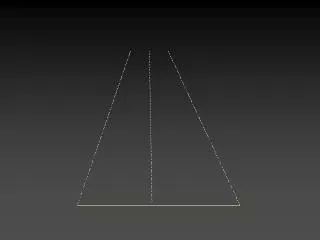
Microwave Landing System (MLS) • Principle of Operation: • Angular position is determined by measuring the time of detection of a beam which is being scanned at a predetermined rate • Example – Azimuth (horizontal): • The azimuth beam is shaped as follows: Top View Side View
Microwave Landing System (MLS) • Principle of Operation: • The beam is fan-shaped, that is, very narrow in the measurement (azimuth) direction and fairly wide in the other (vertical) direction meaning that it can be used at reasonably high angles Top View Side View
Microwave Landing System (MLS) • Principle of Operation: • The beam is swept back and forth at a controlled rate The amplitude of the sweep depends on the requirements of the system but is nominally 40
Microwave Landing System (MLS) • Principle of Operation: • An aircraft thus detects the beam twice per period; once on the “to” sweep and once on the “fro” sweep. The receiver measures the time between the two detections or pulses. t
Principle of Operation - Time Multiplexing • To accommodate all of the required measurements (Az, El, Back AZ and Flare), each is assigned a time slot in a cycle of measurements which takes 115 milliseconds (ms). This is called time multiplexing. Microwave Landing System (MLS)
Dwell Time +40 t 0 T0 -40 • Principle of Operation - Beam Timing: Microwave Landing System (MLS) θ Since the rate of scan and the dwell time are known, the angle θ can be determined from the measurement of t. Where V is the scan rate = 0.02/s
Microwave Landing System (MLS) • The other angle functions are provided in a similar fashion
Microwave Landing System (MLS)Elevation Antenna Installation
Microwave Landing System (MLS) • Airborne Installation: • For the frequency of 5 GHz the wavelength is 6 cm • Thus the antenna (a ¼ wave monopole) is about 1.5 cm long • Receivers are very expensive due to the small market ( about $25,000)
Microwave Landing System (MLS) • Advantages over ILS • Less susceptible to siting (reflection) problems • Selectable glide path angles (up to 20) and azimuth approach paths • Possibility of curved approaches • Much less susceptibility to interference • Many more channels available • Increases runway usability in IFR conditions • Disadvantages • Expensive • Not many ground stations to use it with
Microwave Landing System (MLS) • The Future • Many countries in Europe are interested in MLS for Cat II and Cat III operations because they are getting tired of waiting for LAAS. They are facing much more interference from their FM stations because they are permitted to use much higher power than in North America. • Four MLS facilities were installed at London Heathrow Airport in 2003 and British Airways has equipped 60 Airbus A320 aircraft with receivers. (2003)
Augmented GPS (WAAS, LAAS) • As was mentioned in the section on GPS, the position accuracy can be improved dramatically by the use of differential techniques. • WAAS is capable of accuracies (95%) of • 3.2m horizontally • 6.0m vertically ~ 18 Ft. Cat I Glide Path gives 10 Ft. • This is not quite adequate for Cat I approaches. The vertical error being the problem.
WAAS Approaches • About 525 LPV approaches (Lateral Precision with Vertical Guidance) have been approved. Limits: 300Ft/3/4 mile vis
LAAS Approaches • LAAS promises to provide Cat II and III capability but no approaches have been certified to date
Possible Problem with GPS Approaches • (See Notes)