
Systems Approach
Burglar Alarm Project. Systems Approach. PROBLEM SITUATION. DESIGN BRIEF. DATA SHEETS. SYSTEM ANALYSIS. Evaluation. Build & Test. SPECIFICATION. SOLUTION. Computer Simulation. Resource Selection. Burglar Alarm Project. Problem Situation. PROBLEM SITUATION.

Systems Approach
E N D
Presentation Transcript
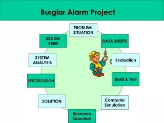
Burglar Alarm Project Systems Approach PROBLEM SITUATION DESIGN BRIEF DATA SHEETS SYSTEM ANALYSIS Evaluation Build & Test SPECIFICATION SOLUTION Computer Simulation Resource Selection
Burglar Alarm Project Problem Situation PROBLEM SITUATION An Alarm company is developing a simple low cost security system for use in a new block of small flats The electronic control sub-system is based on a combinational logic circuit which operates the alarm via a transistor The alarm “arm switch” is incorporated into the the front door key lock. Locking the door will set the alarm giving signal high (1). A Reed switch and magnet are mounted on the door and frame and gives a low(0) signal when the door is opened The pressure mat gives a high (1) output when stood on.
Burglar Alarm Project Design Brief DESIGN BRIEF Design an electronic logic control sub-system to process the signal from the Inputs in order to operate the Alarm buzzer as described above
Burglar Alarm Project Systems Approach PROBLEM SITUATION DESIGN BRIEF DATA SHEETS SYSTEM ANALYSIS Evaluation Build & Test SPECIFICATION SOLUTION Computer Simulation Resource Selection
Burglar Alarm Project Systems Approach The universal System Diagram INPUT PROCESS OUTPUT Any device or system can be analysed in terms of INPUT, PROCESS & OUTPUT
Burglar Alarm Project The universal System Diagram Burglar Alarm INPUT OUTPUT A) Arm Key Activated Z) SCARY SOUND ENERGY B) Burglar Through Door C) Burglar Through Window
Burglar Alarm Project The system diagram can be broken down into a sub system diagram:
Burglar Alarm Project System INPUTS Subsystem Inputs Process Subsystems Subsystem Outputs System OUTPUTS D Push Button N/O Manual Reset Micro Switch N/O AND A LATCH DRIVER Arm Key Activated Reed Switch N/C OR B Inverter BUZZER Burglar Thru Door Z SCARY SOUND ENERGY Pressure Switch N/O C Burglar Thru Window System Boundary Sub System Diagram
Burglar Alarm Project Systems Approach PROBLEM SITUATION DESIGN BRIEF DATA SHEETS SYSTEM ANALYSIS Evaluation Build & Test SPECIFICATION SOLUTION Computer Simulation Resource Selection
Burglar Alarm Project SPECIFICATION The System Must: 1) Detect a Burglar entering through the door or the window 2) Enable owner to disable it to go about their business without setting it off 3) It must give a continuous audible warning to deter burglars, and should be reset by owner 4) It should be low cost, reliable and durable 5) Sensor should be unobtrusive
Burglar Alarm Project Systems Approach PROBLEM SITUATION DESIGN BRIEF DATA SHEETS SYSTEM ANALYSIS Evaluation Build & Test SPECIFICATION SOLUTION Computer Simulation Resource Selection
Burglar Alarm Project SIMULATION LINK Solution
Burglar Alarm Project SIMULATION LINK Solution
Burglar Alarm Project SIMULATION LINK Solution
Burglar Alarm Project SIMULATION LINK Solution
A (Arm Key) B (Reed Switch) C (Pressure Mat) Buzzer 0 0 0 0 0 0 1 0 0 1 0 0 0 1 1 0 1 0 0 1 1 0 1 1 1 1 0 0 1 1 1 1 Burglar Alarm Project SIMULATION LINK Solution
Burglar Alarm Project Systems Approach PROBLEM SITUATION DESIGN BRIEF DATA SHEETS SYSTEM ANALYSIS Evaluation Build & Test SPECIFICATION SOLUTION Computer Simulation Resource Selection
Burglar Alarm Project Selection of Resources Pressure Switch N/O For detecting pressure under mat when burglar comes through window Micro Switch N/O For detecting when door is locked “Arming” the alarm Reed Switch N/C For detecting when the door is open. (This switch is high when the door is closed) Subsystem INPUT Devices
Burglar Alarm Project Selection of Resources Integrated circuits consist of plastic cases filled with electronic circuitry. There are many resistors, transistors and other components packed into the chips. There are literally thousands of ICs on the market, all designed to do different jobs – logic gates, amplifiers, timers, etc. In this work we will be using the TTL (transistortransistor logic) range of chips. TTL chips require a stable 5V supply to work properly. (Great difficulties will be met if any other voltage is used.) Any unconnected pins automatically go to logic 1. In other words, if a wire connected to a pin is connected to the 0-volt rail (logic 0), it will go to logic 0. If the wire is disconnected from the 0-volt rail it will go to logic 1. However, it is good practice to connect pins to ‘high’ or ‘low’ as needed. All TTL chips have a four-digit code number, which always starts with 74. For example, a 7400 is a quad two-input NAND chip. Although the chip contains complex circuitry, the internal wiring can be shown as simple logic circuits with the inputs and outputs of each logic gate shown. This is called a pin-out diagram. Subsystem PROCESS Devices
Burglar Alarm Project AND (TTL 7408) INVERTER (TTL 7408) Used to detect when the arm key is activated AND a burglar is in the system Inverts out put from N/C reeds switch to detect when Door is open OR (TTL 7432) NOR (TTL 7402) 2 cross coupled Nor Gates make an SR FLIP-FLOP Keeping the output high if a burglar closes the door or steps off the mat Used to detect when a burglar comes through the Door OR through the window Subsystem PROCESS Devices
Burglar Alarm Project BUZZER 6v, 30mA For producing Scary Noise Energy at a noise level of 85 db BC 108 NPN Transistor Used for switching and driving the buzzer 10K Ohm Resistor This is a protective resistor used at the transistor base Protective Diode This will protect the the transistor from back emf generated by the buzzer when the Buzzer is reset Subsystem OUTPUT Devices
Burglar Alarm Project Systems Approach PROBLEM SITUATION DESIGN BRIEF DATA SHEETS SYSTEM ANALYSIS Evaluation Build & Test SPECIFICATION SOLUTION Computer Simulation Resource Selection
Burglar Alarm Project DATA ON TTL 74HC04 ‘INVERTER’ CHIP
Burglar Alarm Project DATA ON TTL 74HC32 ‘OR’ CHIP
Burglar Alarm Project DATA ON TTL 74HC08 ‘AND’ CHIP
Burglar Alarm Project DATA ON TTL 74HC02 ‘NOR’ CHIP
Burglar Alarm Project Systems Approach PROBLEM SITUATION DESIGN BRIEF DATA SHEETS SYSTEM ANALYSIS Evaluation Build & Test SPECIFICATION SOLUTION Computer Simulation Resource Selection
Burglar Alarm Project BREAD BOARD
Burglar Alarm Project BREAD BOARD
Burglar Alarm Project BREAD BOARD
Burglar Alarm Project BREAD BOARD
Burglar Alarm Project Systems Approach PROBLEM SITUATION DESIGN BRIEF DATA SHEETS SYSTEM ANALYSIS Evaluation Build & Test SPECIFICATION SOLUTION Computer Simulation Resource Selection