Universal Systems Approach in Technology Analysis
Explore the black box approach to technology analysis using systems diagrams for inputs, processes, and outputs. Learn about open and closed loop control systems along with subsystems breakdown and control diagrams.

Universal Systems Approach in Technology Analysis
E N D
Presentation Transcript
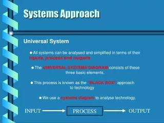
Systems Approach Universal System • All systems can be analysed and simplified in terms of their inputs, process and outputs • The UNIVERSAL SYSTEMS DIAGRAMconsists of these three basic elements. • This process is known as the “BLACK BOX” approach to technology • We use a systems diagram to analyse technology. INPUT PROCESS OUTPUT
Systems Diagrams • To analyse a system more fully, we can list the inputs and outputs from the system. As an example, consider an electric kettle, Water and Electricity. INPUTS: OUTPUTS: Hot water, noise, steam. Hot water, Noise and Steam Water and Electricity KETTLE
Pupil Problems Here are some problems for you to try, • Battery powered torch Chemical energy Light energy Heat energy Torch • Vacuum cleaner Noise, Heat, Clean carpets Electrical energy Dirt Vacuum
Pupil Problems • Washing machine Water, Dirty clothes, Electrical energy Hot water, Noise, Steam, Clean clothes Washing M/C • Television Picture, Sound, Heat Electrical energy, Digital signal TV
Sub-Systems Sometimes it is necessary to break the PROCESS down into smaller pieces. • To enable this we consider the system’s SUB SYSTEMS System Boundary Example: A battery powered torch Light and Heat energy Chemical energy Switch Bulb
Pupil Problems 1) A microwave oven 2nd Subsystems 1st Inputs Timer Set time 5th outputs Magnetron Electrical energy Heat, Light, Hot food On/Off Turntable 3rd Boundary Food 4th Flow of information arrows
Pupil Problems 2) Washing machine Set Cycle Electrical energy Hot water,etc. Control Water Heater Motor Pump Drum Clean Clothes Dirty clothes
Control Systems • All types of system need some form of control to operate • There are 2 main types of control, OPEN LOOP and CLOSED LOOP • In an OPEN LOOP system the input causes the output • The output operates independently of the input • Open loop system are cheap but not very accurate Action Light switch Bulb Light
Control Systems • In a CLOSED LOOP system, the output is compared with a reference value • Closed loop systems are more accurate, but also more expensive • The self monitoring action of closed loop is achieved through a FEEDBACK loop Set temp Thermostat Heat On/Off Motor Fan Heater Elect
Control Systems Manual Open Loop Water Flood Tap Handle Valve Water level Person
Control Systems Manual Closed Loop Correct level Tap Handle Valve Water level Water Eyes / Brain Hand
Control Systems Automatic Closed Loop Water Correct level Press Start Switch Valve Water level Level Sensor Control Unit
Pupil Problems • State three examples of manual open-loop control. Draw a system diagram for each one and show the system boundary. • State three examples of manual closed-loop control. Draw a system diagram and show the system boundary. • State three examples of automatic closed-loop control. Draw a system diagram and show the system boundary.
Control Diagrams Example: Temperature control in a gas oven We could draw a systems diagram for the gas oven, but it is sometimes necessary to draw a more accurate control diagram Set value Gas Valve Burner + - Temperature sensor Oven Correct temperature Actual value
Error Detector Symbol How the error detector works: If SET VALUE (+) is bigger than the ACTUAL VALUE (-) the ERROR SIGNAL is ON (Raising the oven temperature) Set value + Error If the SET VALUE (+) is less than the ACTUAL VALUE (-) the ERROR SIGNAL is OFF (Cooling the oven temperature) - Actual value
Pupil Problems • Explain the following terms when applied to control systems: • Open loop • Closed loop • Error detector
Pupil Problems • Draw a control diagram showing the manual closed-loop control system for a cyclist steering a bicycle. • Draw a control diagram showing the automatic closed-loop control system for the cruise-control in a car.