Download
1 / 13
130 likes | 668 Vues
Airport Needs. Airport is interested in the best achievable minima.An ILS is one means available to achieve those needsEnsuring Feasibility:Obstruction EvaluationAir Space ActionAir Space ActionsRunway length/width, spacing etc. Key Considerations . REAL ESTATEAirport may acquire property 405 Surveys and ResponsibilitiesEnvironmental Assessments and responsibilities Terrain may limit options and Performance of ILS componentsTerrain effects can dramatically increase ALS installatio9460

E N D
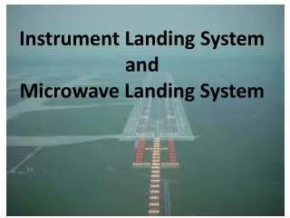
1. Establishment of Instrument Landing SystemsandApproach Lighting Systems
3. Key Considerations REAL ESTATE
Airport may acquire property
405 Surveys and Responsibilities
Environmental Assessments and responsibilities
Terrain may limit options and Performance of ILS components
Terrain effects can dramatically increase ALS installation costs
4. LocalizerCritical Area Requirements
5. Structures Can Impact Localizer performance
6. Glide Slope Critical Area
7. Glide Slope Grading Locate Glide Slope on runway side away from taxiways, roads, etc.
Grading and Obstruction removal
A. Area should be uniformly graded and should have the same longitudinal slope as the runway
B. Area should be smoothly graded to comply with terrain roughness criterion. Extensive landfill operations determined by feasibility.
8. Glide Slope Grading (cont.) C. Area grading may be limited to removal of hills which would reflect the glide slope signal into the usable area.
D. All possible interference sources (metallic structures, fences, etc.) should be removed from areas and that portion that is within 250 feet of the antenna centerline extended.
9. Glide Slope Critical Area
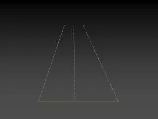
10. MALSR
11. MALSR Approach Light Plane-The light units in the approach light plane are in a single horizontal plane.
At Threshold 400� wide centered on runway centerline.
No object protrudes above the approach light plane. For clearance purposes, all roads, highways, vehicle parking, and railroads are considered vertical solid objects.
12. MALSR (cont.) Visibility- There is a clear line-of-sight to all lights of the system from any point on a surface, on-half degree below the ILS glide paths and extending 250 feet each side of R/W centerline, up to 1600 feet in advance of the outermost light in the system.
13. Web Site�So you want an instrument flight procedure� HTTP://WWW.avn.faa.gov/index.asp?xml=ifp/index