Download
1 / 20
470 likes | 2.47k Vues
Photocatalytic Degradation of Organics. Elizabeth Buitrago University of Arizona Department of Chemical and Environmental Engineering Grad Student Mentor: Mike Schmotzer Faculty Advisor: Dr. Farhang Shadman. Overview. Goals and objectives Introduction/ background

E N D
Photocatalytic Degradation of Organics Elizabeth Buitrago University of Arizona Department of Chemical and Environmental Engineering Grad Student Mentor: Mike Schmotzer Faculty Advisor: Dr. Farhang Shadman
Overview • Goals and objectives • Introduction/ background • TiO2 as a photocatalyst/photocatalytic process • Role of promoters in catalytic oxidation (Ag) • Effects of nitrogen doping in TiO2 • Experimental • Results/Highlights • Future goals
Goals and Objectives • Develop new method for photocatalytic oxidation of organics: • Lower the energy use through catalytic oxidation (UV 185nm used last year--> UV 254 nm used this year) • Reduce the use of chemicals • Remove total organic carbon (TOC) produced by process operations of semiconductor manufacturing
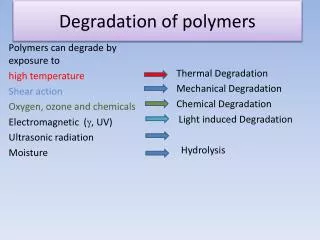
Introduction: Photocatalytic Process Photo-generation electron/hole pairs Formation of radicals Radical oxidation of organic compound.
Role of Promoters in Photocatalytic Process Photo-generation electron/hole pairs Formation of radicals (Ox- radical) Radical oxidation of organic compound. Recombination of electron/hole pair Metal attracts free electron slows recombination and promotes radical formation
Role of Promoters in TiO2 Photocatalytic process Conduction Band e- e- e- e- e- e- e- e- e- e- e- e- e-(M) <-- M+e- Electron/hole pair recombination Electron/hole pair generation Eg Valence Band h+ h+ h+ h+ h+ h+ h+ h+ h+ h+ Metallic promoter attracts electrons from TiO2 conduction band and slows recombination reaction
Effects of Nitrogen Doping in TiO2 Energy TiO2 Bond TiO N Bond 2-x x Orbitals Orbitals Conduction Band Ti d + Ti d + (O2p) O2p +N2p) Ti d Ti d Eg = 3.2 eV Eg = 2.5 eV N2p O2p O2p N2p + O2p O2P + ( Ti d) + ( Ti d) Valence Band Addition of nitrogen increases the size of the bond orbitals, decreasing the energy bandgap
Experimental -Ethylene glycol -urea -Triton X-100 surfactant contaminants -Sol-gel method #1 3-TiO2 layers 3-bakes -Sol-gel method #2 3-TiO2 layers 2-extra TiO2 coats Ag doped before 3rth bake -CVD method N2 doped
Preparation of Supported Catalyst by ChemicalVapor Deposition Method (CVD)Experimental Setup 1 4 TiCl4 reservoir Stripper HP nitrogen cylinder 3 2 Impregnation chamber
Experimental Setup for Batch Reactivity Testing UV lamp 254 nm Water bath/ shaker/ lamp holder Coated screens
Batch Experiments #1 (ethylene glycol) #2 (ethylene glycol) #3 (ethylene glycol) -TiO2 sol gel method -TiO2 method #2 -TiO2 method #1 #1 -Ag/TiO2 method #2 -CVD method -Control -control -Control #4 (Urea) #5 (Triton X-100) #6 (ethylene glycol) -TiO2 method #2 -TiO2 method #2 -CVD/N2 -Ag/TiO2 -Ag/TiO2 method #2 -Control
Results and Highlights Sol-gel method #2 used
Results and Highlights Sol-gel method#2 used
Model for Photocatalytic Reaction 1. Electron/hole formation 2. Electron/hole recombination 3. Radical formation 4. Oxidation of organics 5. Radical combining with X (anything other than TOC) 6. Metal attracts electron = 0 not metal present.
Photocatalytic Model TiO2#1 S = 3.5 CVD S = 10 TiO2 #2 S = 14 cm2 S = active surface area
Photocatalytic Model k · + ¾ ¾ ® + 3 OH TOC CO H O 2 2 Triton X100 k3 = 0.6 ethylene glycol k3 = 0.4 Urea k3 = 0.05
Future Goals • Find new substrates for better deposition of TiO2. • Investigate new ways that would improve our TiO2 loading method. • Improve CVD method. • Improve nitridation method.
Acknowledgments Mike Schmotzer, Dr. Shadman, Sally Clement NSF/SRC for their funding