Exponential Function
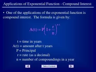
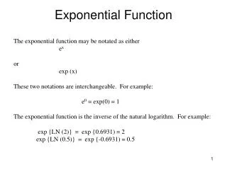
Exponential Function. The exponential function may be notated as either e x or exp (x) These two notations are interchangeable. For example: e 0 = exp(0) = 1 The exponential function is the inverse of the natural logarithm. For example: exp {LN (2)} = exp {0.6931) = 2

Exponential Function
E N D
Presentation Transcript
Exponential Function The exponential function may be notated as either ex or exp (x) These two notations are interchangeable. For example: e0 = exp(0) = 1 The exponential function is the inverse of the natural logarithm. For example: exp {LN (2)} = exp {0.6931) = 2 exp {LN (0.5)} = exp {-0.6931) = 0.5
Exponential Function Usually, the quantity in the exponent is preceded by a negative sign, i.e., e – (somequantity) The function, exp(-x), is called unity exponential decay. When a circuit value grows over time, the exponential function usually finds itself subtracted from 1. This expression 1 – exp(-x) is called unity exponential growth.
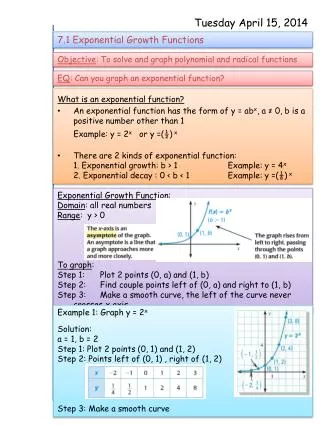
Unity Exponential Decay and Growth unity exponential decay = exp(-x) unity exponential growth = 1 – exp(-x) plateau at 1 note how the curves fall and rise rapidly Figure 14-7 exp(-∞) = 0; 1 – exp(-∞) = 1 – 0 = 1
Exponential and Logarithmic Functions 1. The exponential and natural-logarithm are inverse functions. In other words: ln [exp(x)] = x exp [ln (x)] = x For example: ln [exp (3)] = 3 and exp [ln (3)] = 3
Exponential and Logarithmic Functions: a brief review 2a. There is an interesting property of logarithms that states ln (xa) = a ln (x) Note how the exponent (a) can be thrown in front of the logarithm. For example: ln (32) = 2 ln (3) = 2 * 1.1 = 2.2 Check: ln (32) = ln (9) = 2.2 ✔ 2b. Relationship 2a comes in handy when operating with fractions. More specifically, ln (1/x) = ln (x-1) = - ln (x) i.e., the logarithm of an expression is equal to -1 times the log of its reciprocal for example: ln (1/3) = ln (3-1) = - ln (3) = -1.1
Resistance Reduction Series Circuit a RT = Rab R1 – 3 = R1 + R2 + R3 R1 R2 Resistance between nodes a & b Combined resistance of {R1, R2, R3} Total resistance of the circuit R3 b Parallel Circuit a R1 R3 R2 b
Current & Voltage Dividers Current Divider Voltage Divider
Thevenin & Norton theorems Thevenin To find VTH open circuit network output. Arbitrary Network vTH - Norton To find IN short circuit network output. IN Arbitrary Network
Finding RTH Method 1 To find RTH divide the Thevenin voltage by the Norton current. RTH=ETH/IN Method 2 Arbitrary Network To find RTH short all voltage sources and open all current sources. Next, find the equivalent resistance of the series and parallel mesh. RTH
RMS values of various AC sine waves Vrms sine wave = 0.707 Vp Vp sine wave = 1.414 Vrms The generic expression for a voltage sine wave is v(t) = Asin(2ft) A= amplitude (volt) f = frequency (in hertz) t = time (in seconds)
Op Amp Input Voltage (Verror) • The op amp has two voltage signal input pins labeled Vinv(–, inverting input) and Vni(+, non-inverting input). Verror = Vni–Vinv • For the ideal op amp, Iinv and Iniare zero amperes.
Op Amp Output Voltage Vout op amp= AVerror Where • Vout op amp= output voltage of the op amp • A = voltage gain of the op amp • Verror= input voltage to the op amp
Op Amp Output Voltage Limitations Vlower rail≤Vout op amp≤Vupper rail • Once the output hits one of the rails, the op amp is said to be saturated.
Op Amp Input Voltage Limitations –Esupply < Vinv Vinv< +Esupply • If either input voltage is outside the supply range, some of the components (namely, diodes and BJTs) would be biased improperly.
Sine wave driving an op amp comparator (example) V lower rail = - V upper rail =13 figure 12.43a figure 12.43b VinAv = Vout [sin (2pft)](105) = 105 sin (2pft) wrong ! The op amp has an upper rail voltage limit of +13V with a +15V supply, and a lower rail voltage limit of -13V with a -15V supply, due to an overhead voltage of 2V. Vupper rail = 15V – 2V = +13V Vlower rail = -15V + 2V = -13V
Sine wave driving an op amp comparator (example) figure 12.43b figure 12.43a What size input is required to bring the output to the positive rail ? V+input = 13V / 105= 1.3mV Similarly, the minimum voltage to bring the output to the negative rail is: V- input = -13V / 105 = -1.3mV
Definition of inverting and non inverting comparators a) Non-inverting comparator circuit. b) Inverting comparator circuit.
Generating the offset voltage Esupply V upper rail E supply -Esupply V lower rail Pick a value for R1 and solve for R2 R1+R2 = Esupply (R2) / Vref R1= [Esupply(R2) / Vref] – R2
Inverting Schmitt Trigger Transfer Function Vout The complete transfer characteristics
Inverting Schmitt Trigger B is the return feedback factor abbreviations: UTP = upper trip point LTP = lower trip point
Operational amplifier voltage gain Inverting Av = -Rf / Ri Non-Inverting Av = 1 + Rf / Ri Buffer Av = 1
Inverting operation amplifier with bipolar power supplies. Example with AC signal input with no DC offset :voltage gain = Av = 1 + Rf / Ri = 1 + 3.3kW / 1kW = 4.3 (dimensionless)
Buffer op amp with bipolar power supplies:example with AC signal input with no DC offset
Non-inverting op amp with bipolar power supplies:example with AC signal input with no DC offset voltage gain = Vout / ein = Av = -Rf / Ri = -3.3kW / 1kW = -3.3
Capacitive Reactance • The opposition of capacitance to ac current is termed capacitive reactance (XC). The magnitude of capacitive reactance is Where • XC = capacitive reactance (Ω) • f = frequency of the ac sinusoidal signal (Hz) • C = capacitance (F) Note: XCcannot be simply added to resistance magnitudes: resistance dissipates energy reactance shares energy
Universal approach to solve for the DC transient • Step 1: Find vC(0-) Find the capacitor voltage just before the switch is closed. • Step 2: Find the time constant of an RC circuit is = RC. If this is a complex circuit other than a simple RC circuit, then first determine the Thevenin equivalent circuit using the capacitor as a load. Next, use the Thevenin resistance = RthC continued ...
Universal approach to solve for the DC transient Step 3a: Draw the modeled initial current (or Thevenin circuit) properly model the capacitor as a short or voltage supply. + E 0 V E initially charged capacitor initially uncharged capacitor figure 14-12 Step 3b: Find the desired initial voltages and currents. continued ...
Universal approach to finding the DC transient Step 4: Draw the steady-state circuit of the Thevenin circuit. (figure 14-13) Properly model the capacitor as an open, then calculate the steady-state voltages or currents of interest. continued ...
Universal approach to finding the DC transient Step 5: If needed, write and apply the universal transient DC equation for the desired voltages and currents. Then, simplify the equation. y(t) = Yss + (Yinit – Yss) exp (-t / t) Step 6: If needed, sketch all the voltages and currents that are being evaluated. All simple RC circuits (or Thevenin-modeled RC circuits) can be solved with this six-step process.
Inductive Reactance • The reaction of an inductor to an ac current is called the inductive reactance (XL) XL = 2πfL Where • XL = inductive reactance to an ac sinusoidal signal () • f = frequency (Hz, hertz) • L = inductance (H, henries) Inductive reactance is in units of ohms, like resistance, but cannot be directly added to resistance magnitude: - resistance dissipates energy - reactance stores energy
Relaxation oscillator Charging and discharging times are the same if the clipping points of the op amp is symmetrical RC ln [ (1 + b) / (1 – b) ] = t The time period for a complete cycle of the waveform is T = 2t The frequency of the waveform is f = 1/T = 1/(2t)