FLOW-SHEETING
FLOW-SHEETING. What we will cover here? PFD? Preparation and presentation of PFD P&ID? Preparation and presentation of P&ID. FLOW-SHEETING. PFD? A shorter version of process flow diagram A key document of process design

FLOW-SHEETING
E N D
Presentation Transcript
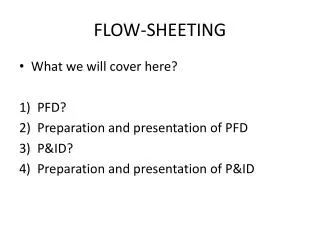
FLOW-SHEETING • What we will cover here? • PFD? • Preparation and presentation of PFD • P&ID? • Preparation and presentation of P&ID
FLOW-SHEETING • PFD? • A shorter version of process flow diagram • A key document of process design • Shows the arrangement of the equipment, the streams connection, streams flow rates and composition and the operating conditions. • Diagrammatic model of the process
FLOW-SHEETING • PFD? • Used as the basis for the next steps in the design, including piping, instrumentation, equipment design and plant layout. • Drawn up from material balances made over the complete process and each individual unit operation.
FLOW-SHEETING • PFD? • Most calculations on PFD are carried out using commercial process simulation software.
FLOW-SHEETING • FIG 4.1
FLOW-SHEETING • FIG 4.2
FLOW-SHEETING 2) PFD Preparation and Presentation Essential Infos: • Stream composition, either - Flow rate of individual component (kg/h) or as weight fraction b) Total stream flow rate, kg/h c) Stream temperature (oC) d) Stream pressure • Fig 4.1/ 4.2A (with some modification): What I expect in your design project.
FLOW-SHEETING 2) PFD Preparation and Presentation Layout - Sequence of the main equipment items shown symbolically on the PFD follows that of the proposed plant layout. - Some license must be exercised in the placing of ancillary items, such as heat exchangers and pump, or the layout will be too congested
FLOW-SHEETING 2) PFD Preparation and Presentation Layout • The equipment should be drawn approximately to the scale. • Should be drawn in correct proportion. • Ancillary items can be drawn out of proportion. • For a complex process, several sheets may be needed, and the continuation of the process streams from one sheet to another must be clearly shown.
FLOW-SHEETING 2) PFD Preparation and Presentation Layout • Fig 4.2 shows one method indicating a line continuation. • Table of stream flows and other data (T, P) can be placed above/ below the layout. (Fig 4.2) • The stream line numbers should follow consecutively from left to right of the layout
FLOW-SHEETING 2) PFD Preparation and Presentation Layout • All the process streams should be numbered. Batch Process • Normally show the quantity required to produce one batch. • If, a batch process forms part of an otherwise continuous process, it can be shown on the same flow sheet, providing a clear break is made when tabulating the data between the continuous and batch sections. i.e., the change from kg/h to kg/ batch.
FLOW-SHEETING 2) PFD Preparation and Presentation Batch Process • In a case where a batch process included in a continuous process, the flow usually labelled as ‘Normally no flow’, and show the flow rates that will be obtained when the stream is flowing.
FLOW-SHEETING 2) PFD Preparation and Presentation Utilities. • Usually only headers and lines were shown in the process flow sheet. Equipment Identification -Must be identified with a code number a name. H-xxxx (Heat exchanger), R-xxxx (Reactor), C-xxxx (Column).
FLOW-SHEETING • What we will cover here? • PFD? • Preparation and presentation of PFD • P&ID? • Preparation and presentation of P&ID
FLOW-SHEETING 3) The P and I Diagram • Shows the arrangement of the process equipment, piping, pumps, instruments, valves and other fittings, It should includes; a) All process equipment identified by an equipment number. Should be drawn roughly in proportion, and the location of the nozzles shown.
FLOW-SHEETING b) All pipes, identified by line number. The pipe size and material of construction should be shown. The material may be included as part of line identification number. c) All valves, control and block valves, with an identification number. The type and size should be shown. The type may be shown by the symbol.
FLOW-SHEETING d) Pumps, identified by a suitable code number e) All control loops and instruments, with an identification number. f) Process information is not shown.