Boundary-Scan driven Vectorless Testing on Active Components
Boundary-Scan driven Vectorless Testing on Active Components. Steve Hird Loveland, CO. Purpose. Describe a methodology that extends Boundary-Scan driven Vectorless test to include active components. Outline. Review Existing technology used for connectors


Boundary-Scan driven Vectorless Testing on Active Components
E N D
Presentation Transcript
Boundary-Scan driven Vectorless Testing on Active Components Steve Hird Loveland, CO
Purpose Describe a methodology that extends Boundary-Scan driven Vectorless test to include active components.
Outline • Review Existing technology used for connectors • Examine the unique challenges of active components • Examine some target devices • Conclusions
Using Boundary-Scan for Test Stimulus in VTEP test. • Combine Boundary-Scan drivers with TestJet/VTEP sensors. • Use Boundary-Scan drivers in place of In-Circuit drivers for guarding and stimulus, but retain capacitive pickup of signal.
Using Boundary-Scan for Test Stimulus • What are the advantages of this ? • Test pins whose signals are not accessible • Can eliminate access (cheaper fixtures) • Validates the investment in Boundary-Scan
Boundary-Scan interface Picture from paper 11.2 ITC 2008. Using Boundary-Scan for Test Stimulus What are the advantages of this ?
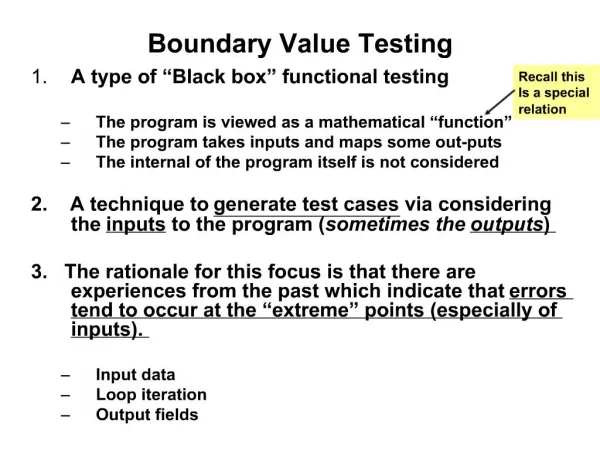
What are the challenges with active components? • Silicon devices require accurate setup information. • Connectors require very little pin information for test generation. Most of the information is external and gathered from the node data. All pins are considered either fixed or inputs.
Required Setup Information • Pin orientation: Input, Output, Bidirectional • Disabling information (DUT): All bidirectional, output and buffer pins require disabling • Disabling all devices involved in test (connected to DUT)
Incomplete Disabling Problems • Sequential logic creates variability in response • Signals may add or cancel from run to run • Causes high standard deviation.
Standard Deviation and Testability • Cpk = (Mean-LL)/(3 x Std Dev) • Cpk 1.5 = 99.865% Yield • Cpk 1.0 = 93.3% Yield
Experimental ResultsSi Parts Evaluated – DDR2 * Coverage before resolving issues discussed on next two slides.
DDR2 FBGAs are Challenging but Testable • Small part geometries and lead frame yield small signal on Vtep Sensor plate • Care must be taken to minimize on board noise sources
Si Parts Evaluated – SRAM, DRAM * Coverage before resolving issues discussed on next two slides.
Results of Experiments • Learnings • Noise from surrounding circuits should be minimized for best results • Disable DUT and connected devices for test stability and increased coverage • Lead frame geometry plays important role (similar to any Vtep test)
Conclusion • Active components can be tested using Boundary-Scan driven Vectorless Test Technology • Proper disabling is critical • Eliminating on board noise sources will increase coverage • Technique reduces need for access