ECE 001 Lego Robot Project
150 likes | 390 Vues
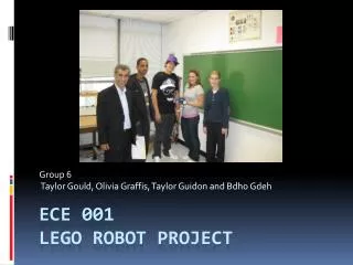
Group 6 Taylor Gould, Olivia Graffis, Taylor Guidon and Bdho Gdeh. ECE 001 Lego Robot Project. Purpose. Build a robot out of Legos that would enable movement along a flat surface Design code ( C interactive ) that would be implemented within the handyboard to instruct the robot to:

ECE 001 Lego Robot Project
E N D
Presentation Transcript
Group 6 Taylor Gould, Olivia Graffis, Taylor Guidon and Bdho Gdeh ECE 001Lego Robot Project
Purpose Build a robot out of Legos that would enable movement along a flat surface Design code (C interactive) that would be implemented within the handyboard to instruct the robot to: Move along a path from a start point to a finish line being guided by a thick black line of tape Perform a U-turn and then follow the black line back to the starting point
Resources • Handyboard • (2) Motors • (2) Top-hat sensors • Lego Kit including wheels and corresponding rubber tires • C Interactive computer program with connecting wires to attach to computer 1"HandyBoard Layout.” 2 The Handyboard
Method • Constructed a chassis and a base for the robot • It had to be large enough to place the handyboard on along with the two motors • We built walls around the base to enclose the handyboard in • The 2 motors were placed on the back end of the machine • Wheels were attached to rods with gears (increasing torque) running through to the base of the motors • Lastly, the light sensors were added to the front of the robot, being placed approximately 5 mm from the ground. • Paper formed into cones were wrapped around the base of the sensors in order to prevent outside interference and coordinate anchorage to the machine.
Code • This is the final code used in the program to direct the robot down the path, along the black line, make a U-turn at the end, and then return in the same manner to the other end. • Commands such as “int” defined the variables (“Flag1,” “Flag2”) as integers, whereas, “if” and “while” statements were utilized to form the loops necessary to complete the program. • Since the robot completed a U-turn, the while loop was broken up in order to form another loop so that the robot would stop the second time it’s sensors encountered darkness on both sides of the robot. void main () { int Flag1, Flag2; int sensor1, sensor2; while (!start_button()); Flag1=1; Flag2=1; while (Flag1==1) { sensor1= analog(4); /*right*/ sensor2= analog(5); /*left*/ if ((sensor1<150 && sensor2<150)) { motor (1, 50); /*motor1*/ motor (2, -50); /*motor 2*/ } if ((sensor1<150) && (sensor2>150)) { motor (1, 75); motor (2, 10); } if ((sensor1>150) && (sensor2<150)) { motor (1, -10); motor (2, -75); } if ((sensor1>200) && (sensor2>200)) { ao(); Flag1=0; } } motor(1, 70); motor(2, 50); sleep(0.7); while(analog(4)<135) { motor(1,50); motor(2,50); } ao(); while(Flag2==1) { sensor1= analog(4); /*right*/ sensor2= analog(5); /*left*/ if((sensor1<150 && sensor2<150)) { motor (1, 50); /*motor1*/ motor (2, -50); /*motor 2*/ } if((sensor1<150) && (sensor2>150)) { motor (1, 75); motor (2, 10); } if((sensor1>150) && (sensor2<150)) { motor (1, -10); motor (2, -75); } if((sensor1>200) && (sensor2>200)) { ao(); Flag2=0; } } }
Challenges • Design of the robot • Tested periodically throughout the project to ensure that the best combination of Lego design and the necessary technological features interacted symbiotically • Light sensors failed to work. • Taped small paper cones around the sensors so the light would be absorbed in a specific area • The robot would occasionally make its U-turn early • Tests completed on various tracks; outside light (mostly unevenly distributed shadows) was disrupting the sensors readings
3 Forces Acting on a Centrifuge A centrifuge is a piece of equipment that is driven by a motor which rotates an object around a fixed axis at very fast speeds. This acceleration and centrifugal force separates one fluid from another fluid based on greater and less density. There are numerous different types of centrifuges and they can be used to accomplish a variety of different tasks. Examples of these include isotope separation, separation of macromolecules, separation of oil components as used in the petroleum industry, oil-water separation as we completed in our experiment as well as other commercial applications. Centrifuges have an especially important role in biomedical studies. Centrifuge Experiment 4 Commercial Centrifuge
Experimental Set-up • Lego pieces, gears and motors were used for assembly • Created a sturdy base that would support the fast rotation • Positioned the gears, motors and cuvette holder • Added counterweight on opposite side Note: Many modifications to the design were made to achieve our final model of the centrifuge
Code The source code that we used to carry out the centrifuge experiment was separated into two parts. This first part spun the suspension around an axis: void main() { inti; /*We define the different variables that we are going to use in the experiment*/ intj; ints; while(start_button()==0); for(i=10; i<=100; i=i+10) { motor(1,i); sleep(0.2); } sleep(5.0); for(j=0; j<=100; j=j+10) { s=100-j; motor(1,s); sleep(0.2); } } The second part of the code used a top-hat sensor to read the density of the different parts of the suspension: void main() { while(start_button()==0); while(1) { printf("\n mixed up value=%d", analog(6)); /*This displays the light reading using th top-hat sensor and gives us the results for our experiment*/ sleep(0.5); } }
Raw Data The table below demonstrates the results from the readings from our centrifuge experiment.
Conclusions • The combination of both code-writing and structural design forced the group to adapt to the challenges that were presented, and work together to solve problems by testing and reformatting the experimental design • Improvements • The sensors could have been more exact in evaluating the amount of lightness or darkness • As a result, it reduced the robot to a jerky motion in response to radical changes in darkness and is likely to have relayed the robot to a slower performance when turning to avoid the black tape line. • This produced inconsistent values for the centrifuge and is likely to have prevented constructive data values for assessment • For better stability along the track and maximum velocity attainment, the combination of wheels and weight would be altered
Works Cited • "HandyBoard Layout." Chart. The Handyboard How to Guide. 29 Sept. 2006. Council Rock South Technology Club. 12 Nov. 2008 <http://www.southtech.org/handyboard/images/handyboard_layout.gif>. • The Handyboard. Digital image. Digital Sketchbook Computer Graphics 530: Continued Development of Human-Art Interaction. 22 Jan. 2004. Syracruse University. 12 Nov. 2008 <http://web.syr.edu/~dfmoore/log/530.html>. • Rumley, Regina, John Whichard, Rachel Rosenberg, and Katie Knupp. The Forces Acting in a Centrifuge. Digital image. The Physics of a Centrifuge. 2008. The University of North Carolina at Chapel Hill. 6 Nov. 2008 <http://www.unc.edu/~reginara/>. • Generalic, Eni. Centrifuge. Digital image. Ilustrated Croatian-English Chemistry Dictionary & Glossary. 2005. Croatian Ministry of Science, Education and Sports. 12 Nov. 2008 <http://www.ktf-split.hr/glossary/en_o.php?def=centrifuge>.