Download
1 / 1
80 likes | 536 Vues
Design and Simulation of a MEMS Piezoelectric Micropump Alarbi Elhashmi, Salah Al-Zghoul, Advisor: Prof. Xingguo Xiong Department of Biomedical Engineering, University of Bridgeport, Bridgeport, CT 06604. Abstract. 2000um.

E N D
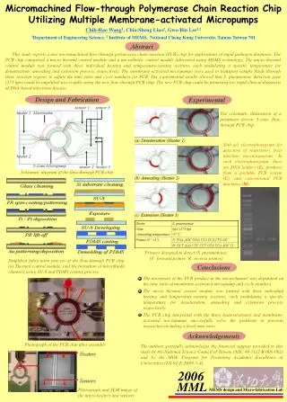
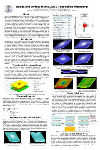
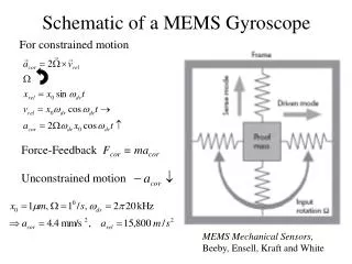
Design and Simulation of a MEMS Piezoelectric Micropump Alarbi Elhashmi, Salah Al-Zghoul, Advisor: Prof. Xingguo Xiong Department of Biomedical Engineering, University of Bridgeport, Bridgeport, CT 06604 Abstract 2000um Table 1. The optimized design parameters of the MEMS Piezoelectric Micropump 600um MEMS micropumps are important components for many bioMEMS devices such as Micro Total Analysis System (μTAS), Lab-on-a-chip, and microdrug delivery systems. Many activation techniques can be used in pumping the microfluid in MEMS pumps; among them, piezoelectric activation is an attractive one due to its low cost and simple fabrication. In this poster, the design and simulation of a MEMS piezoelectric micropump is proposed. The device consists of top and bottom silicon structures that are bonded together. Two valves are embedded in the pump on the both side: one inlet, and one outlet. In addition, the piezoelectric material is bonded on the diaphragm on the top part. When voltage is applied to the piezoelectric actuator, the membrane bends down and up, which makes the inlet and outlet valves open and close, with both valves moving in the same direction. Hence, fluid is pumped into the chamber from the inlet valve and pumped out from the outlet valve. A theoretical model is used to analyze the working principle of the micropump. Based on analysis, a set of optimized design parameters are suggested. ANSYS simulation has been used to verify the function of the device. A fabrication flow has been suggested for the fabrication of the micropump. The proposed micropump can be used for various bioMEMS applications. 800um 1200um 400um 800um 4000um 1200um Figure 4. Dimensions of the top view Piezoelectric Micropump Introduction Micropumps are MEMS (Microelectromechanical Systems) actuators used to drive microfluid to flow toward certain destination. Micropumps usually refer to the pumps that are fabricated on the scale of microns (1μm=10-6m). Various micropumps based on different actuation techniques have been reported, such as electrostatic micropumps, piezoelectric micropumps, thermodynamic micropumps, smart polymer micropump, magnetic micropumps, etc. Among them, piezoelectric micropumps are attractive designs due to their easy operation and large pumping force. In a piezoelectric micropump, a pumping chamber is connected to inlet and outlet ports, with one-way microvalves to regulate the pumping flow direction. The pumping chamber is sealed by top diaphragm, with a piezoelectric actuator deposited on top of it. When AC driving voltage is applied, piezoelectric actuator will expand and shrink periodically, causing the diaphragm to bend up and down. Hence the microfluid is sucked into the chamber from inlet, and pumped out from outlet periodically. Due to their small size, low cost, low power consumption, and high efficiency, micropumps have been widely used in many applications in the field of Biomedical Engineering such as Micro Total Analysis System (μTAS), Lab-on-a-chip, and micro drug delivery systems. Figure 6. Second vibration mode of micropump (f = 0.641kHz) Figure 5. First vibration mode of micropump (f = 0.634kHz) Piezoelectric Micropump Design Figure 8. Fourth vibration mode of micropump (f = 0.826kHz) Figure 7. Third vibration mode of micropump (f = 0.817kHz) In this poster, a bulk-micromachined piezoelectric micropump is proposed. The proposedmicropump consists of two parts: top and bottom silicon structures with piezoelectric material located in the top diaphragm. Both top and bottom structures are shown in Figure 1. In the top silicon structure, it is a square shape that has a gap in the middle. The square shape also has two inlet and outlet valves. In the bottom silicon structure, it has a gap in the middle with two openings. Both top and bottom structures are bonded together via silicon direct bonding technique. When the piezoelectric material bends the diaphragm down, the outlet valve will open to allow fluid to exit the system while the inlet valve will be closed and vice versa. Figure 9. Fifth mode of piezoelectric micropump (pumping mode, f = 0.862kHz) 1 2 1 - Diaphragm 2 - Piezoelectric Actuator 3 - Top cover 4 - Valve 5 - Chamber 6 - Bottom Structure 3 4 5 6 Figure 10. Sensitivity analysis when experiencing pressure of 10 MPa Figure 11. Stress contour plot when experiencing pressure of 10 MPa Device Fabrication Figure 1. 3D view of the structure of a MEMS Piezoelectric Micropump The device is fabricated with bulk-micromachining process, as shown in Figure 12. The top and bottom silicon structures are fabricated with DRIE (Deep Reactive Ion Etching) etching separately. Aluminum is used as etching mask for Si DRIE etching. After that, the top and bottom structures are aligned and bonded together with Silicon Direct Bonding (SDB) technique. The steps are listed as follow: (1) deposit Al layer on Si wafer; (2) photolithography to define the chamber and valves; (3) etching a small area to define the chambers of the pump; (4) Remove Al layer and re-deposit Al layer as etching mask; (5) Use photolithography to define the valves (6) mask-less etching until the valves structure are formed (7) the bottom structure will follow the same steps. (8) top and bottom structures are aligned and bonded together with silicon fusing bonding, device is fabricated. For each selective silicon etching, it has seven sub-steps: (1) Oxidation; (2) Photoresist spinning; (3) Photoresist patterning; (4) Al etching; (5) Photoresist removal; (6) Silicon DRIE etching; (7) Al removal. During the bonding process, precise alignment is required to ensure the proper function of the device. Theoretical Analysis Assume the diameter, thickness, and operation voltage of the PZT material are d, h and u separately, the frequency of operation is f (~60 Hz). The resulted flow rate of the micropump can be derived by calculating the stroke volume. Since the PZT material in design has a square shape, we can approximate the diameter by calculating the volume of a cube and comparing it with the volume of a cylinder. In our micropump design, the diameter is 902.7 µm. Vstroke = 8 x 10-11 x (d / h) x u Vstroke = 4.15 x 10⁻¹² µL Flow rate = Vstroke × f = 4.15 x 10-2 X 60 = 2.49 µL/sec = 149.9 µL/sec Design Optimization and Simulation Fabrication process of top structure Based on theoretical analysis, we derived a set of optimized design parameters of the piezoelectric micropump, as shown in Table 1. According to the design parameters, the piezoelectric micropump has the intrinsic vibration frequency of 60 Hz. ANSYS FEM simulation is used to extract the vibration modes as well as the stress distribution of the device. The bending shape of the diaphragm structure under given voltages can also be observed. The ANSYS simulation results are in good agreement with theoretical prediction. The first five vibration modes and the corresponding resonant frequencies of the micropump are shown in Figures 5 – 9. 3. DRIE etching of Si 2. Photolithography 1. Deposit Al layer Fabrication process of bottom structure 4. DRIE etching of Si 5. Photolithography 4. Deposit Al layer Bonding of top and bottom structures Conclusions and Future Work Figure 12. Fabrication flow of the micropum (cross-sectional view) In this project, a bulk-micromachined piezoelectric micropump design is proposed. The working principle of the micropump is analyzed in details. The bending of diaphragm and pumping rate of the micropump are derived. Based on the analysis, an optimized design is suggested. ANSYS simulation is used to verify the performance of the device. The fabrication flow of the device is also proposed. The fabrication is based on Si DRIE etching and silicon direct bonding (SDB) techniques. In the future work, we will further improve the device’s performance, such as increasing the pumping flow rate and reducing the driving voltage of the micropump. Figure 2. Undeformed shape of the micropump (top structure) Figure 3. Undeformed shape of the micropump (bottom structure)


![Modeling MEMS Sensors [SUGAR: A Computer Aided Design Tool for MEMS ]](https://cdn2.slideserve.com/5124381/modeling-mems-sensors-sugar-a-computer-aided-design-tool-for-mems-dt.jpg)