Download
1 / 5
50 likes | 149 Vues
Benefit from zero dead time, increased algorithm capacity, user-selected functions, and effortless block division with our innovative DSP system design. Discover how to implement zero death time, install new algorithms, select user functions, and integrate modules without conflict. Explore a range of high-performance ADC components for your system needs.

E N D
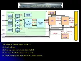
This design has some advantages as follows: (1). Zero Dead time. (2). More algorithms can be installed into the DSP. (3). User can select the functions which he wants. (4). Divide each block into individual module without conflict.
(1) Zero death time (implement method): (1) Digitalize most circuit (2) Zero death time (3) Use DSP to develop algorithms usingUS patent 5304808 Stage1 Stage2 adopt from D.M.C. Odell, B.S. Bushart, L.J. Harprting, F.S. Moore, and T.N.. Riley,“Zero dead time spectroscopy without full charge collection”, Nuclear instruments and methods in physics research, vol.A.422, p363-367, 1999
(2) More algorithms can be installed into the DSP: (A) Model Fitting (Stage 3) Adopt from J.B.P.SSimoes, P.C.P.SSimoes, C.M.B.A.Correia, “Nuclear spectroscopy pulse height analysis based on digital signal processing techniques,” Nuclear Science Symposium and Medical Imaging Conference, Vol. 2, 1994. (B) Data compress (Under estimate) (3) User can select the functions which he wants: (A) Select functions from DAQ software. (B) Using JUMPERs to select module function. (B.1) Change system frequency from setting (C) Add small LCD to display system state.
(4) Divide each block into individual module without conflict: Processing Prepare Finish
ADC component : ------------------------------------------------------------------------------------------------------------------------------------------------ (1) AD9203 (40Mhz,10bits,both) Analog Device ($8.3, Popular, BW 400Mhz) Get ------------------------------------------------------------------------------------------------------------------------------------------------ (2) ADC10040 (40Mhz,10bits,both) National Semiconductor (Cheapter $4.7)Get (3) ADC10D040 (Dual 40Mhz,10bits, both) National Semiconductor (Cheapter $9)Get ------------------------------------------------------------------------------------------------------------------------------------------------ (4) AD5103 (40Mhz,10bits,only) Texas Instrument($5.25, BW 950Mhz) Get (5) AD5121 (8 channels 40Mhz,10bits,only) Texas Instrument($39, BW 22Mhz) Get (6) THS1040 (40Mhz,10bits,both) Texas Instrument($5.1, BW 900Mhz) Get ------------------------------------------------------------------------------------------------------------------------------------------------ (7)MAX1444 (40Mhz,10bits,both) Maxim/Dallas ($5.25, BW 400Mhz) Wait (8) MAX1168(Dual 40Mhz,10bits,both) Maxim/Dallas($9, BW 400Mhz) Wait (9) MAX1190 (120Mhz,10bits,both) Maxim/Dallas ($19.95, BW 400Mhz) Wait ------------------------------------------------------------------------------------------------------------------------------------------------