1 / 9

HCAL HV splice box

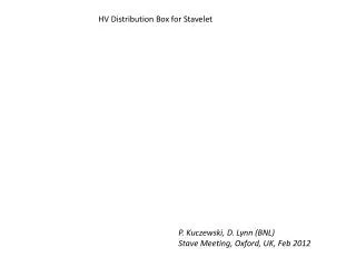
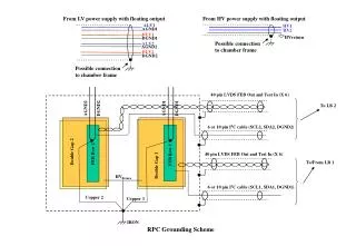
HCAL HV splice box. HV cable: 4 thick wires – HV ( up to 15 kV) transfer; 7 thin wires – bias voltages (< 100 V) transfer; Shield – to ground on RBX side. To ground. Splice Box , general view. Metal case of splice box is grounded. Shield. Splice Box, side and top view. To ground.

jenna-booth
Télécharger la présentation

HCAL HV splice box

An Image/Link below is provided (as is) to download presentation Download Policy: Content on the Website is provided to you AS IS for your information and personal use and may not be sold / licensed / shared on other websites without getting consent from its author. Content is provided to you AS IS for your information and personal use only. Download presentation by click this link. While downloading, if for some reason you are not able to download a presentation, the publisher may have deleted the file from their server. During download, if you can't get a presentation, the file might be deleted by the publisher.

E N D

Presentation Transcript


  1. HCAL HV splice box

  2. HV cable: 4 thick wires – HV ( up to 15 kV) transfer; 7 thin wires – bias voltages (< 100 V) transfer; Shield – to ground on RBX side. To ground

  3. Splice Box, general view Metal case of splice box is grounded.

  4. Shield Splice Box,side and top view To ground

  5. View on line AA, one channel Silicon compound RTV112 - Dielectric Strength – 16 kV/mm Isolation of HV splice connection

  6. Connector for BV wires

  7. Photo of Splice Box Metal case of splice box is grounded.

  8. Connection of HV cable to detector (RBX)

  9. Connection of HV cableto HV power supply

More Related