Monitoring splice resistances
Monitoring splice resistances. M. Koratzinos 25 February 2009. I ntroduction. The QPS system, apart from protecting magnets from quenches, can also measure and monitor splice resistances.

Monitoring splice resistances
E N D
Presentation Transcript
Monitoring splice resistances M. Koratzinos 25 February 2009
Introduction • The QPS system, apart from protecting magnets from quenches, can also measure and monitor splice resistances. • The so-called ‘snapshot’ method of the QPS system was used during October-December 2008 for finding out abnormal splice resistances. • Two splices with abnormal resistance were found (one at about 100nOhm and the other at about 50nOhm) during that campaign.
Inventory of splices in the main circuits • The main LHC circuits (where the largest proportion of the energy is stored) – the MB circuit and the MQ circuit, include a certain number of splices. • We have splices inside the cold mass (magnet splices) and splices between magnets (inter-magnet splices) • The number of splices per magnet can be seen in the following slides:
RB bus • Magnet splices: • 4 inter-layer splices per magnet • 2 inter-pole splices per magnet • 1 inter-aperture splice per magnet • 1 internal bus splice per magnet • Inter-magnet splices • Two inter-magnet splices per interconnect
Simplified diagram of splices, inductances and voltage taps, RBA EE112 EE111 EE113 = RB bus = inter-layer splice = inter-aperture splice EE211 = inter-pole splice EE212 = bus splice EE213 = inter-magnet splice = coil = voltage tap EExxx EE013 EE012
Simplified diagram of splices, inductances and voltage taps, RBB EE015 EE014 EE013 EE012 EE111 = RB bus EE112 = inter-layer splice = inter-aperture splice EE113 = inter-pole splice = internal bus splice = inter-magnet splice EE211 = coil = voltage tap EExxx EE213 EE212
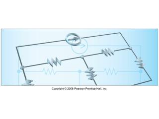
The RB bus A B Q C
Current QPS measures four voltages: EE112 EE111 EE113 = RB bus = inter-coil splice = inter-aperture splice EE211 = inter-pole splice EE212 = internal bus splice EE213 = Coil = Voltage tap EExxx Bridge A = [V(EE112) – V(EE211)] –[V(EE211) – V(EE213)] Bridge B = [V(EE111) – V(EE113)] –[V(EE113) – V(EE212)]
nQPS – MB bus (MQ similar) – this will monitor inter-magnet splices V V Current implementation
Remarks on RB splices • Current QPS system is sensitive to all magnet splices but one • A modification to cover all splices is being considered – the technical constraints and implications are being evaluated
nQPS – MB bus (MQ similar) – a possible implementation V V Proposed change
RQ bus • Here the two apertures are powered independently by the MQF/MQD circuits • Magnet splices: • zero inter-layer splices per magnet • 3X2 inter-pole splices per magnet • zero inter-aperture splice per magnet • 4 internal bus splices per magnet • Inter-magnet splices • 4 inter-magnet splices per interconnect
MQ EE251,EE252 EE151,EE152 EE231,EE232 EE131,EE132 EE014, EE015 EE012,EE013 EE211,EE212 EE111,EE112 = RQF, RQD bus = inter-pole Splice = bus Splice = inter-magnet Splice EE022,EE023 EE024, EE025 = Voltage tap = Coil EExxx Courtesy K. Schirm
Remarks on RQ splices • As per dipole circuit, the four internal bus splices are not monitored by the QPS system. • A similar modification to the system (as in the RB case) will allow the monitoring of those splices as well
Conclusions • It is desirable to monitor as many splices as possible in the LHC electrical circuits. • A (minor) modification will allow the new QPS system to monitor all splices of the main circuits of the LHC, both inside a magnet and inter-magnet. • Technical implications are being considered, but we believe that if technically possible, we should implement it.