Auto Splice Conductivity Analyzer (ASCA)
Auto Splice Conductivity Analyzer (ASCA). ENSC 440/ENSC 305 15 December 2009. Getting to know the team. Shamsul Hoque (Sam) Chief Executive Officer Amir Najafzadeh Chief Financial Officer Zhouhao Cui (Joe) Chief Technical Officer Milad Moezzi Chief Marketing Officer. Outline.


Auto Splice Conductivity Analyzer (ASCA)
E N D
Presentation Transcript
Auto Splice Conductivity Analyzer (ASCA) ENSC 440/ENSC 305 15 December 2009
Getting to know the team • Shamsul Hoque (Sam) • Chief Executive Officer • Amir Najafzadeh • Chief Financial Officer • Zhouhao Cui (Joe) • Chief Technical Officer • Milad Moezzi • Chief Marketing Officer
Outline • Motivation • Team Members’ Roles • Team Dynamics • System Overview • High Level System Design • Alternative Solution • Marketability • Future Upgrades
Outline (cont’d) • Environmental Considerations • Project Specifics • Lessons learnt • Conclusion • Resources • Acknowledgements • Questions • Low Level System Details
Outline • Motivation • Team Members’ Roles • Team Dynamics • System Overview • High Level System Design • Alternative Solution • Marketability • Future Upgrades
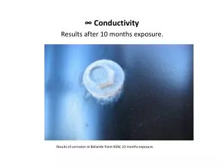
Motivation (cont’d) ACSR Wire Splice in a Transmission Line Splice Faulty Splice
Motivation (cont’d) • Dangers of a faulty Splice • Loss of power and electricity transmission • Live wire may fall on ground! • May even cause electrocution and forest fires!!
Motivation (cont’d) • A typical splice lasts about 20-30 years. Why change it if there is no damage? • After researching expensive not-so-effective existing solutions, we were looking for an alternative
Outline • Motivation • Team Members’ Roles • Team Dynamics • System Overview • High Level System Design • Alternative Solution • Marketability • Future Upgardes
Team Members’ Roles • Zhuohao Cui (Joe) • Hardware Design • Software Implementation • Research and Development • ShamsulHoque (Sam) • Research and Development • Quality Assurance • Documentation
Team Members’ Roles (cont’d) • Amir Najafzadeh • Research and Development • Hardware Design • Budgeting • MiladMoezzi • Marketing and Finances • Hardware Design • Troubleshooting
Outline • Motivation • Team Members’ Roles • Team Dynamics • System Overview • High Level System Design • Alternative Solution • Marketability • Future Upgrades
Team Dynamics • Efficient weekly meetings were held • Each member was assigned tasks with specific deadlines • Disagreements were overcome maturely • Progress was monitored on a weekly basis
Outline • Motivation • Team Members’ Roles • Team Dynamics • System Overview • High Level System Design • Alternative Solution • Marketability • Future Upgrades
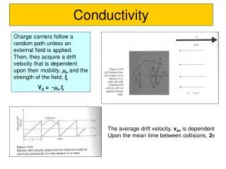
System Overview (Theory) • An alternating magnetic field is generated around a conducting wire • Due to corrosion and other factors, as splices deteriorate, conducting wires slowly loose contact • As strands start becoming inactive, a change in magnetic field intensity can be observed • A Hall Effect Sensor or other sensors can be used to measure this alternating magnetic field intensity
Outline • Motivation • Team Members’ Roles • Team Dynamics • System Overview • High Level System Design • Alternative Solution • Marketability • Future Upgrades
High Level System Design (cont’d) Operational Algorithm
High Level System Design (cont’d) • Control Unit • Hall Effect Sensors • Microcontroller • Voltage Regulators • Shifter Circuit • Software
High Level System Design (cont’d) • Hall Effect Sensors • are able to measure magnetic field intensity directly in to mili volts (mV), once placed near a current conducting splice • can measure a wide range of magnetic field strengths unlike other sensors An actual size HE Sensor
High Level System Design (cont’d) • Microcontroller • Once input data has been collected by the Hall Effect Sensors, a Arduino Duemilanove board processes this data • The board has a Atmel ATmega328 chip. It also has a built in analog to digital data converter Arduino Duemilanove PIC board
High Level System Design (cont’d) • Microcontroller • There is a built in 32 kilo bytes (KB) flash memory, which is more than enough to store sufficient data for one scanning process. After each scanning process, stored data is reset. • There is a dedicated software provided by the manufacturer free of cost which is related to this board Arduino Duemilanove PIC board
High Level System Design (cont’d) • Shifter Circuit • Tests were carried out on a overhead cable. • When only one strand was conducting current the output voltage was 2.4401V • When all the strands were conducting current the output voltage was 2.508 V Voltage Regulator circuit to provide a constant Vcc for a Shifter circuit
High Level System Design (cont’d) • Shifter Circuit • This provided a very small range of 60.7 mV to determine a splice’s health • We need a shifter circuit to map the 2.4401-2.508V range to 0-5V range • We also need a voltage regulator to make sure the Op Amp receives constant voltage supply from the source Shifter circuit calculations and results
High Level System Design (cont’d) • User Interface Unit • LCD • This LCD does not require an additional power source to operate. It can be powered using the power from the microcontroller • LEDs • The green LED is used to show that data is within optimal range. • The red LED is used to indicate data is out of range. • The blue LED lights up when data is irrelevant or there is insufficient data.
Outline • Motivation • Team Members’ Roles • Team Dynamics • System Overview • High Level System Design • Alternative Solution • Marketability • Future Upgrades
Alternative Solution (cont’d) • Infrared Thermography Technique • Use infrared cameras to detect hot spots. • This process can detect hot spots to determine failures only at later stages of a splice’s life under certain conditions • Wind flow and weather conditions can significantly impact test results
Alternative Solution (cont’d) • Resistance Measurement • A properly installed splice has lower resistance than that of a similar length conductor. • It should have a resistance of 30%-80% of the conductor; i.e., the ratio is 0.3-0.8. Any splice with a ratio greater than 1.2 will heat up and show abnormality. Replacements should be made if the ratio goes over 2.0
Alternative Solution • X-Ray/Radiography Method • Improper installation or misplaced splices can be a major cause of splice failures. • But this is not an accurate indication of a failed splice as proper placement and alignment do not assure lifetime connection. • It is a costly method to carry out
Outline • Motivation • Team Members’ Roles • Team Dynamics • System Overview • High Level System Design • Alternative Solution • Marketability • Future Upgrades
Who would be interested in the product? • Power transmission cable companies • Auto-Splice makers • Power line maintenance companies • Tie-line data management companies • Between countries • Between provinces and states • Turbine cross-cables, induced machine cables
Cost • Cheap i.e. 90-100$ • Even cheaper if mass produced • No other product with same accuracy and simplicity • Accuracy- Rises as testing period decreases • Simplicity- Simple to use, maintain • Way cheaper, when compared with power losses and hazards associated
Cost • Reduces operation cost, from engineering, or high level positions to technicians • As it takes few minutes for each connection point. Big savings on overall costs • Very feasible
Competitors • Thermal testing • Costly • Inefficient • Hard to operate • Node by Node • Only operational when cable has already failed • Power shut off • Hard to test and replace in harsh climates
Outline • Motivation • Team Members’ Roles • Team Dynamics • System Overview • High Level System Design • Alternative Solution • Marketability • Future Upgrades
Future Upgrades • Hall Effect Sensor Noise Reducing Circuit • This is a very simple circuitry that might be used to reduce introduced noise. • This circuit can be particularly useful where the data is irrelevant and can be filtered out.
Future Upgrades (cont’d) • Integrating Hot Stick and separating the user interface unit • The ASCA device has multiple power sources. This gives the device added portability and a chance to power/operate the device from a laptop or an alternating power source. • In future models, for instantaneous observations, the user interface unit can be separated and held in hand while the rest of the device is mounted on overhead wire. For this model to be produced, wiring needs to be incorporated with the hot stick.
Outline (cont’d) • Environmental Considerations • Project Specifics • Conclusion • Resources • Acknowledgements • Questions • Low Level System Details 44
Time Line • Started On Time ? • Meet The Deadlines ? • The Outcome ?
BUDGET What we paid for: • Arduino Micro Controller $45 • LEDs $3 • LCD Display $17 • Bread Board $21 • Hall Effect Sensors $50 • Regulators $1 • Wireless Circuit $25 • Battery $35 • Electric Kettle $25 • Transmission Cable $70 Total $292
COST • Designed to be cheap • Estimated Unit Price: $100
Software • Programming micro-controller i.e. Arduino • Applied C++ to coding and debugging • LCD display coding and encoding • Control of different components in the circuit, i.e. sensors, LEDs, LCD • Timing, between the data captures and desired time