PICAM Status
PICAM Status. Klaus Torkar (IWF Graz) for the PICAM Team SERENA-HEWG Meeting, Key Largo, FL, 17 May 2013. Contents. PICAM basics QM status and test results Front-end ASIC (TIMPO32) status FM status and schedule. P lanetary I on CAM era.

PICAM Status
E N D
Presentation Transcript
PICAM Status Klaus Torkar (IWF Graz) for the PICAM Team SERENA-HEWG Meeting, Key Largo, FL, 17 May 2013
Contents • PICAM basics • QM status and test results • Front-end ASIC (TIMPO32) status • FM status and schedule
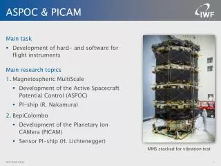
PlanetaryIonCAMera • All-sky camera for charged particles to investigate the exo-ionosphere composition and distribution • Hemispherical instantaneous field of view to measure the 3-D velocity distribution and mass composition of ions at high resolution Main contributions: IWF/OAW (Austria)LATMOS, LPP (France)MPS (Germany)WIGNER (Hungary)STIL (Ireland)ESTEC
Science Performance Requirements • PICAM-related requirements from the Science Performance Report
Ion Optics Principle Annular input slit Start gate Mirror M1 Mirror M2 Toroidal analyzer Detector
Ion Optics Layout • Ions enter through an annular slit (1) • After reflection on an ellipsoidal mirror (2) the ions pass through a gate (3), and the 90° polar angle distribution is folded to a narrow range. • Through a slit (4) the ions enter a toroidal analyzer (5) for energy selection. • Through exit slit (6) the ions enter the mass analysis section consisting of a plane mirror (7) whose geometry and potentials are set to optimize the resolution of the TOF measurements, and finally hit the MCP (8). 2 1 – entrance window, 2 – primary mirror, 3 – gate, 4 – secondary slit, 5 – toroidal analyzer, 6 – exit slit, 7 – secondary mirror, 8 – MCP detector Ion beams with entrance polar angles 0° (green), 45° (red), and 90° (blue)
Ion Optics Design Update • Deflecting electrodes (6) allow for the correction of any misalignment between first mirror and electrostatic analyser • Converging lens (4) improves polar angle resolution • Retarding grid (5) - if activated - may improve the mass resolution
Anode Group Arrangement • Grouping of anodes is necessary to reduce data volume • Modes will be selected to support the various scientific objectives No image (TOF only) Full image 4 groups 7 groups
Time-of-Flight Measurement • Standard method: gate opens briefly and remains closed until the slowest ions in the passing packet have hit the MCP low efficiency • Random sequence (Hadamard code) at gate & deconvolution high efficiency (~50% of the ions pass) TOF spectrum before deconvolution after deconvolution
Power versus Performance • Hadamard mode may be used below several 100 eV depending on code frequency • For higher ion energies, single pulses will be used
Operating Modes • PICAM can simultaneously produce two data products: • Primary science data: • TOF spectra averaged over few or many pixels, for each out of typically 32 energy steps, typical sampling intervals 8 s to 64 s per data set • Secondary (survey) data: • Omnidirectional TOF spectra + full resolution images (31 pixels) without mass discrimination, both at 32 energies, variable sampling intervals up to several minutes • Common to both data sets are the settings for the energy sweep and the gating (single pulses or Hadamard codes)
Imaging Modes • Without mass discrimination • Three different image resolutions • Primary telemetry with 8 or 32 s time resolution • Secondary TM with full image but 64 s time resolution 8 s 32 s
Mass Discrimination and Combined Modes • 4 modes with mass discrimination, without imaging • 4 modes with combination of limited mass resolution and imaging • Primary telemetry with 32 s time resolution, 16 or 32 E-steps • Secondary TM with full mass spectrum integrated over FoV, but only 64s time resolution
Modes Selected as Baseline • 1 imaging mode: mainly used at Apoherm • 1 mass mode: mainly used at Periherm • 1 combined mode: mainly used at Periherm
Pre-Calibration Examples Angular distribution Energy resolution E = 1 keV ΔE1/2/E ~ 11% ΔE1/2 ~ 110 eV Numerical model, 1 keV ions Numerical model, 1 keV ions ΔE1/2/E ~ 4% E ~ 1.015 keV ΔE1/2 ~ 40 eV QM measurement, ions N2+, 1 keV QM measurement, ions N2+, 1 keV
Pre-Calibration Examples Simulation of the time of flight for masses 23 (Na) and 24 (Mg) T ~ 2.81 µs T/ΔT1/10 ~ 28 ΔT1/10 ~ 0.1 µs T/ΔT1/10 ~ 21 T ~ 5.72 µs ΔT1/10 ~ 0.28 µs Measured TOF with QM, ions N2+ , 300 eV Resolution in this case was driven by gate pulse duration, not by geometry
Pre-Calibration Examples Mass resolution may exceed values of the numerical model, provided that gate pulse duration is properly set T ~ 2.81 µs T/ΔT1/10 ~ 28 ΔT1/10 ~ 0.1 µs T ~ 3.15 µs T/ΔT1/10 ~ 39 ΔT1/10 ~ 0.08 µs Measured TOF with QM, ions N+andN2+ , 1000 eV
QM Status • QM has been successfully vibrated and shock tested • Functional testing and calibration has started • Angular, energy, and mass resolution have been characterised • Further future improvement of angular and mass resolution by fine-tuning internal voltages is expected • Calibration will be resumed as soon as possible after the ongoing thermal vacuum test, for as long as possible • Open work includes implementation of compression for PICAM data in the SCU • Thermal vacuum test is ongoing • Challenging set-up to achieve wide temperature range (-90°...+240°C) for outer parts in a single facility • Test is split into cruise phase and Mercury orbit qualification
TIMPO Issues • Latch-up and SEU susceptibility of TIMPO ASIC detected during heavy-ion tests in October 2012 • Mainly in analogue part due to wrong choice of decoupling capacitors • Also some sensitivity in digital part • New ASIC will be developed, availability not earlier than Dec 2013 • Use of existing ASIC studied as an alternative, but it will suffer from very frequent latch-ups • Additional electronic protection circuit mandatory for both versions • Circuit requires new detector electronics layout and new layout of DPU • Re-design of ASIC already completed • Funding of delta qualification testing is under negotiation
FM Status • Some FM components already delivered • Electronics not affected by TIMPO changes is under manufacture • Protection electronics development for the TIMPO and the delta qualification testing of the TIMPO drive the FM schedule • QM has to be temporarily delivered to system as FM substitute
Summary • The QM is under environmental testing and calibration • Key performance parameters have been verified, but calibration is not yet complete and further tuning of the instrument is advisable • Major current issue is the schedule and funding of the front-end ASIC modification and related work • QM has to be delivered temporarily as FM substitute • FM with modified ASIC and additional protection electronics will not be ready before late summer 2014