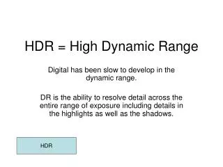
Light Detection with Ultra-High Dynamic Range
This project focuses on improving fluorescence microscopy to study conformational and functional changes in protein channels. Given the low signal-to-noise ratio (SNR) of approximately 0.1%, the team was tasked with developing a system that minimizes noise while maximizing signal detection. Key solutions include optimizing lens selection, reducing thermal noise by cooling, and employing advanced filtering techniques, such as Bessel and Butterworth filters. The project aims to ensure accurate monitoring of subtle protein interactions through precise signal amplification and filtering, thus aiding Dr. Jon Silva's research.

Light Detection with Ultra-High Dynamic Range
E N D
Presentation Transcript
Light Detection with Ultra-High Dynamic Range Group 35 DoHyun Kim, Leran Firer, and Eric Kleinberg Client: Prof. Jon Silva
Project Review - Client Request • Dr. Silva’s studies conformational and functional change of protein/protein channels by using a fluorescence microscopy.
Project Review - Client Request • Background Signal ≈ nA • Signal of interest ≈ pA→ SNR is approximately 0.1% → Client requested to build a system with a higher SNR by reducing noise • Reducing Noise • By matching Lens and PIN diode • By lowering temperature of the system • By Input constraint and Filtering system withExternal circuit
Light Focusing System cont’d • Chosen solution: Achromatic Doublet Lens
Lens Assembly Simply insert lens into c-mount using twisting action. C-mount fits in microscope.
Design: Electrical System _ PIN Diode Selection • Responsivityat 600 nm wavelength • Low Noise: Thermal Noise + Dark Current Noise • Low Capacitance • Operating Temperature • Size of active area
Design: Electrical System _ PIN Diode Selection • PIN-HR(S)008(L) Specification
Design: Electrical System _ Input Constraint • Why? • In Real OP Amps, small current (μA ~ pA) flows inside of OP Amps, generating Voltage error. • Solution: Current to Voltage Converter
AC Current to Voltage Converter • Literature Search: A low-noise and wide-band ac boosting current-to-voltage amplifier for scanning tunneling microscopy • Tunneling Microscopy • Specialized current to voltage converter for pA to nA Current. • Unity Gain at 5 kHz to 10 kHz
Design: Electrical System _ Filter • Domain of Frequency of interest: 5 kHz to 10 kHz • Preserve the shape of the original signal! • Solutions • Analog Filter • Active Bandpass Filter: Bessel Filter • Digital Filter
4th order Bessel Bandpass Filter Design • Center Frequency FM= 7.5KHz • Bandwidth B= 5kHz • Q= FM/B = 1.5 • Center Gain Km = 1 (absolute value); it’s is an unity gain filter • From the Coefficient of the 4th order Filter Table a1 = 1.3617 b1 = 0.6180α = 1.2711 (at Q = 1.5) • Fm1 = FM/ α = 5900.4Fm2 = FM* α = 9533.3 • C = 10 nF
4th order Bessel Bandpass Filter Simulation Design Failed
Filter – Digital Filter • Axon™ Axopatch™ 200B microelectrode Amplifier • Bessel & 4-pole Butterworth Filter • Bandwidth: 30Hz to 5kHz • Delay: Unknown
OP Amplifier Design • Inverting Amplifier
Assembly of the Circuits • Soldering on Printed Circuit Borad (PCB)
Assembly of the Circuits Schematics for Multi-purpose OP AMP PCB • PCB will be drilled and screwed to the cylinder in which adopted into the SM1 Adopter of the head-stage.
Peltier Cooler Analysis • Normally calculation is performed based on an expected thermal load in Watts. • In our case, there is no load. The PIN diode must be cooled relative to ambient temperature. • Team discussed this with an engineer at Tellurex, a Peltier Cooler Company. • His advice was to pick a Peltier that fit our size constraints, and to then adjust the cooling amount by increasing or decreasing the DC current applied to the cooler.
Design Safe • Lack of Grounding. • Improper Wiring • Inadequate Heating/Cooling of Peltier (Heat Sink) • Wastes: Defective Parts
Conclusion • Failed to properly design Bessel Filter. • All other design requirements were properly attained. • No IP.