MAV Optical Navigation Software Subsystem
This project focuses on creating an optical navigation software subsystem for Micro Air Vehicles (MAVs), including flapping-wing types. It aims to enable semi-autonomous operation in closed environments by allowing user-selected destinations and real-time navigation output. Utilizing tools such as OpenCV and JavaCV within the Netbeans IDE, the system addresses object discovery, tracking, and recognition, while ensuring collision avoidance through 3D environmental modeling and path planning. Future enhancements will include improved machine learning algorithms and user interfaces.

MAV Optical Navigation Software Subsystem
E N D
Presentation Transcript
MAV Optical Navigation Software Subsystem October 28, 2011 Adrian Fletcher (CECS), Jacob Schreiver (ECE), Justin Clark (CECS), & Nathan Armentrout (ECE) Sponsor: Dr. Adrian Lauf
Background – Micro Air Vehicles (MAVs) • A subset of Unmanned Aerial Vehicles (UAVs) • Predator • Raptor • Very small, maneuverable, and lightweight • MAV Categories • Fixed-wing • Rotary-wing • Flapping-wing • Used for homeland & battlefield applications • Surveillance • Reconnaissance
Background – Dr. Lauf • Dr. Lauf is a new assistant professor in the CECS department from Wright State University • His research is in embedded system design with applications to UAVs and MAVs • Communications & Networking • Controls • Navigation • Autonomous Flight • Multi-Agent Systems Courtesy of Dr. Lauf
Background - Dr. Lauf’s MAVs • Flapping-Wing MAV • Sensors are limited to • Gyroscopes (MEMS) • 3-Axis Accelerometers (MEMS) • Monocular Camera with Transceiver Unit • Optical Navigation is necessary for autonomous operation Courtesy of Dr. Lauf
Flapping-Wing MAV Example Courtesy of Dr. Lauf
Purpose • Develop a optical navigation software subsystem • User selected destination • Semi-autonomous operation • Adaptable for flapping-wing MAVs • Operates in closed, static environment • Classroom with tables and chairs • No moving objects
Operational Concept • Preflight operations • Calibrate the camera • Place the test rig in the room • Start the optical navigation software • Choose a destination • Mid-flight operations • Move camera to simulate flight • Follow suggested navigational output
System Requirements and Restrictions • Requirements: • Communicate real-time navigation output • Create 3D model of the environment • Plan a path from current location to a selected destination • Work in any closed, static environment • Restrictions • Non-stereoscopic camera
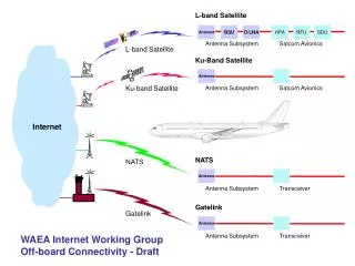
Hardware Architecture • Two major components • Camera transceiver unit • Computer with vision software • Connected via 1.9Ghz RF channel
Software Tools • OpenCV • JavaCV • Netbeans 7.0.1 Integrated Development Environment (IDE)
OpenCV with JavaCV • OpenCV: open source computer vision software library built by Intel Corporation • Image Processing • Object Recognition • Machine Learning • 3D Reconstruction • JavaCV: a wrapper for OpenCV • Allows us to use OpenCV in Java environment • Includes added functionality
Netbeans 7.0.1 • Free, open source IDE • Supports multiple languages including Java • Includes many developer helper functions • GUI & Form Builder • Software Debugger • Unit Testing • Code completion • Integrated subversion (SVN)
Object Discovery • Goal: Find a prominent object in view • Why: Need to initialize object tracking and learning • How: Use the “Snake” algorithm • Based on active contour detection • “Constricts” around strong contours
Object Tracking • Goal: Provide short-term tracking capability in the learning phase is the same object • Why: Assist long-term (learning) tracker • How: • Lucas-Kanade optical flow algorithm • Uses scattered points on object to track motion • CamShift algorithm • Reduces picture color and calculates color histograms
Object Recognition • Goal: Establish a model for an object during the learning phase • Why: • Recover from object occlusion • Provide a basis for egomotion (camera motion) • How: • SURF algorithm • Haar-Like features • Machine learning
3D Reconstruction • Goal: Establish no-fly zones for the current environment • Why: • Collision avoidance • Path planning • Data visualization • How: Egomotion recovery with stereo vision techniques
Path Planning • Goal: Provide navigational output to user • Why: Builds framework for autonomous navigation • How: • Modified navigation algorithms
Graphical User Interface (GUI) • Goal: Provide data visualization and user input capability • Why: • Destination selection • Navigational output • Internal troubleshooting • How: • Netbeans GUI builder
Camera Calibration & Test Rig • Applications • Camera calibration • Verification of egomotion estimation
Completed Tasks • Integrated JavaCV & OpenCV with Netbeans 7.0.1 IDE • Interfaced with a variety of cameras • Camera calibration & test rig built
Future Work • Module integration • Object recognition • Object tracking • Machine learning • 3D Reconstruction • Obtain depth perception • Egomotion & Stereo techniques • Destination selection • Path Planning • Improved Graphical User Interface (GUI)
Hybrid-mode autonomous navigation for MAV platforms Adrian P. Lauf, P. George Huang Wright State University Center for Micro Aerial Vehicle Studies (CMAVS) Guidance and Control Local Control Loops • Unlike traditional UAVs, MAVs have limited power and computational resources • Qualify as deeply-embedded systems • Weight restrictions are primary obstacle for onboard processing systems • In some cases, aircraft weigh less than 7 grams • The need for autonomy requires the integration of on-board and off-board processing and guidance capabilities • This hybrid schema permits computationally-intensive operations to run without weight restrictions • Various sensor inputs can be used to aid local and global navigation objectives • Video camera images • MEMS gyroscopes • Other heterogeneous mounted sensors • MEMS-based gyroscopes onboard GINA provide information about the aircraft’s stability • Simple PID control can be used to keep aircraft level and stable • Filtering functions can mitigate hysteresis caused by wing motion and control surface actuators • Onboard microprocessor is capable of handling these high-rate, low-complexity tasks • Feedback from PID control can be sent off-board for processing via 802.15.4 radios • Actuator control can be directly handled by the microprocessor; inputs to the system from external sources do not directly actuate control surfaces An airframe and drivetrain example of a CMAVS flapping-wing aircraft Existing receivers and actuators Off-board Control On-board Hardware • Off-line image analysis permits identification of navigation objectives and obstacles • Frame-to-frame analysis allows the system to construct a model of its environment and surroundings • Information contained in the world-model can be used to make navigation decisions • Multiple-aircraft implementations can more quickly and accurately build world-model • Permits joint and distributed operation in an unknown scenario • Allows distributed agents to augment the accuracy of existing models • Commands issued as a result of image analysis can be used as inputs into the PID control navigation routines onboard the aircraft • Each MAV (Micro Aerial Vehicle) equipped with on-board computing module • Guidance and Intertial Navigation Assistant (GINA) • Based on schematics developed at UC Berkeley’s WarpWing project • Modified to reduce weight, unneeded components • Onboard processing allows for vehicle stability in flight • Integrated IEEE 802.15.4 radio protocol permits two-way radio communications • Radio telemetry • External commands • Video image capture and transmission • Without modification, GINA 2.1 weighs over 2.2 grams. • Development will target a weight of 1.5 grams or less Gyroscope output from a GINA module A base-station mote used for the off-board computer