Design Principles of the CMS Level-1 Trigger Control and Hardware Monitoring System
This paper discusses the design principles of the CMS Level-1 Trigger Control and Hardware Monitoring System in particle physics, including the project context, problem complexity, and management methodology.

Design Principles of the CMS Level-1 Trigger Control and Hardware Monitoring System
E N D
Presentation Transcript
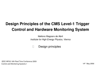
Design Principles of the CMS Level-1 Trigger Control and Hardware Monitoring SystemIldefonsMagrans de AbrilInstitute for High Energy Physics, Vienna • Project context • Problem complexity • Design principles IEEE NPSS 16th Real Time Conference 2009 Control and Monitoring Systems I 14th May 2009
Particle physicist Electromagnetic Calorimeter: Measure energy of particles interacting electromagnetically Project context Hadronic Calorimeter: Measure energies of particles interacting via the strong nuclear force ? Silicon Tracker: Find charged particle tracks and measure momenta Muon detector: Find muon tracks and also measure momenta
Solution based on two filter levels: Level-1 Trigger (HW) High Level Trigger (SW) 40 million events/second ~55 million Channels ~1 Mbyte per event What is there between CMS and the particle physicist? Control system: coordinates experiment operation It is feasible to store O(100) events/second
…To control and monitor… HARDWARE L1 Decision Loop and detector front-ends. SOFTWARE Experiment Control System What is this project about?
Configuration: • 64 crates • O(103) boards • Firmware ~ 15 MB/board • O(102) regs/board The L1-Trigger Decision Loop • Testing: • O(103) links
L1-Trigger Control and Hardware Monitoring System: Provides a machine and a human interface to operate, test and monitor the Level-1 decision loop hardware components. • Run Control and Monitoring System (RCMS): • Overall experiment control and monitoring • RCMS framework implemented with java (8) Experiment Control System • Cross-platform Data AcQuisition middleware (XDAQ): • C++ component based distributed programming framework • Used to implement the distributed event builder • Detector Control System (DCS): • Detector safety, gas and fluid control, cooling system, rack and crate control, high and low voltage control, and detector calibration. • DCS is implemented with PVSSII
Why is this a complex work? • P4: • Periodic upgrades • Unforeseen operational needs P1: Large distributed HW system P3: Limited SW engineering background P2:Complex integration management
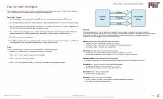
P2: management complexity P4: unforeseen requirements Management methodology What did we propose? Distributed architecture = stable abstraction P1: Large distributed HW system P4: periodic upgrades P3: background and interests Subsystem integration facilities
P2: management complexity P4: unforeseen requirements Management methodology Distributed architecture = stable abstraction P1: Large distributed HW system P4: periodic upgrades P3: background and interests Subsystem integration facilities
HTTP/CGI:Automatically generated Control panel plug-ins + e.g. DTTF panel e.g. GT panel e.g. Cell FSM operation Synchronous and Asynchronous SOAP API • Xhannel infrastructure: • Designed to simplify access to web services (SOAP and HTTP/CGI) from operation transition methods • Tstore (DB) • Monitor collector • Cells FSM Plug-ins The Cell • Other plug-ins: • Command: RPC method. SOAP API extensions • Monitoring items
P2: management complexity P4: unforeseen requirements Management methodology Distributed architecture = stable abstraction P1: Large distributed HW system P4: periodic upgrades P3: background and interests Subsystem integration facilities
Hierarchical control system 1 central cell per sub-system ~ STABLE ABSTRACTION OF THE L1T Multicrate subsystems ~ 2 levels of subsystem cells (1 subsystem central cell)
P2: management complexity P4: unforeseen requirements Management methodology Distributed architecture = stable abstraction P1: Large distributed HW system P4: periodic upgrades P3: background and interests Subsystem integration facilities
e12() e23() e34() S4 S1 S2 S3 New operational capabilities can be coordinated by particle physicist managers without SW expertise Management methodology e43() Particle physicist manager Subsystem SW developer e12() e23() e12() e23() S1 S2 S3 S1 S2 S3 Entry cell Operation states Operation transitions Operation transition methods Service test
P2: management complexity P4: unforeseen requirements Management methodology Time complexity Trigger Supervisor design summary Distributed architecture = stable abstraction Scale complexity P1: Large distributed HW system p4: periodic upgrades p3: background and interests Subsystem integration facilities Human complexity