Download
1 / 17
170 likes | 191 Vues
Troubleshooting and resolution plan for optics alignment, camera triggering, and software issues to improve image quality and system performance in a controlled environment.

E N D
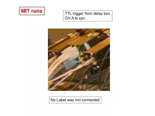
MIT runs TTL trigger from delay box CH A to syn syn no label No Label was not connected
SMD Camera Manual Description DATA SYNC NO LABELED
RG39 Cable from TTL converter to “NO LABEL”, NOT “SYNC” This Photo shows the previous connection when I did “Manual” Triggering. NOT CURRENT CONFIGURATION SWITCHED When I received it, The BNC adaptor was connected to “NO LABELED” SMA connector. External Triggering did not work. CONFIRMATION : Currently the BNC adapter is switched to “SYNC” External Triggering did work. syn no label TTL trigger from delay box CH A to “SYNC”, NOT “No Label”
Current Configuration in Tunnel One BNC adaptor to “SYNC” TTL Module is disconnected
http://www.epixinc.com/products/ttlmod.htm Converts TTL Trigger to Differential for input into PIXCI Board Converts PIXCI Board Differential Strobe Output to TTL We don’t need this TTL module. So I disconnected the RS-39 cable. Camera is triggering using BNC input through “SYNC” as we did at MIT.
Lens mount alignment : The gap between camera and objective lens was very small. The focusing adjuster roatated stiff. Camera holding bar and XY stage holding bar Were rotated. NOT WELL MOUNTED NOW. IT WAS ASSEMBLED AT BNL. NEVER DISASSEMBLED AFTER IT LEFT BNL. • “pcmerit08” is installed. • - outlet : 3009/15 • (3 outlet left in tunnel) • IP address : 137.138.184.21 • connected to iboot4
Current Scope Trace Triggered Time T (Master Triggering) = To To from DG535 T (Master Triggering) = To Synchronized Laser Pulse Triggering Signal from GaGe Board Output 17 pulse, 0.1 ms period Delay from To was about 0.005 ms. SMD Camera Triggering Signal. A from DG535 A = To + 0.000000000 s Photodiode signal from scintillating fiber
Viewport 1, Sep. 5, 2007 Viewport 1, Sep. 13, 2007 Brightness changes suddenly. Possibly optics problem. The edge is very sharp. Possiblely optics may got damaged. Circle is shifted. Alignment is broken. Window is not clear.
Viewport 2, Sep. 5, 2007 Viewport 2, Sep. 13, 2007 Window is not clear. Brightness changes suddenly. No field of view is visible.
Viewport 3, Sep. 5, 2007 Viewport 3, Sep. 13, 2007 Focusing of left side was changed. Alignment changed slightly. ALMOST SAME
Viewport 4, Sep. 5, 2007 1 ms fps 0.05 ms shutter 1 W laser used. CW pulse for 0.5 s 12db+12db attenuator used Able to use same control input signal with FV camera.
Viewport 4, Sep. 13, 2007 0.1 ms fps 17 frames Read Out 25 W laser used. 0.1 ms period laser pulse 17 pulses, total 1.7 ms light Laser Insensity is LOW 17 frames Read Out
Viewport 4, Sep. 13, 2007 External Triggeirng Camera “Trigger IN” 1.7 ms fps 1 frames Read Out 25 W laser used. 0.1 ms period laser pulse 17 pulses, total 1.7 ms light Field of View is visible clearly OBJECTIVE LENS IS NOT WELL MOUNTED
Viewport 4, Sep. 13, 2007 External Triggeirng Camera “Trigger IN” 0.5 ms fps 4 frames Read Out Frame does read out correctly corresponding to the laser time. 25 W laser used. 0.1 ms period laser pulse 17 pulses, total 1.7 ms light
Viewport 4, Sep. 13, 2007 1W laser, 0.5s CW pulse, 0.5 ms fps 0.5 ms fps 17 frames Read Out SWITCHED to 1 W Laser CW for 0.5 s
Moving Fan image Manual triggering 0.1 ms fps. 17 frames. 8, 12(default), 16 bit file save support. jpg, tif, …etc support. Possible to save files Independently. Possible to save files in one file. But the file size Increases up to 10 Mbyte because it saves all of the buffer Images (180EA). Software shows like this. Not real No 14 degree rotation Different with previous software
CONFIRMATION • ALL COMPUTERS / EQUIPMENT ARE ABLE TO DO POWER RECYCLE • AND CONTROL REMOTELY AND ALL 4 IBOOT IS WORKING • SMD CAMERA IS WORKING CORRECTLY AND RESPOND CORRECTLY TO • THE EXTERNAL TRIGGERING INPUT • - ALL 4 CAMERAS WORK SIMULTANEOUSLY • THINGS TO BE RESOLVED • SHOULD OPEN THE SNOUT AGAIN AND INSPECT OPTICS STATUS • AND THEN REPAIR/REALIGN OPTICS. BE PREPARED FOR THAT. • PREREQUISITE : THOMAS SHOULD COME AND COOPERATE WHEN THERE IS A CHANCE TO OPEN THE SNOUT. WE HAVE ONE EXTRA OPTICS-FIBER SET. JUST IN CASE, WE CAN REPLACE ONE VIEWPORT. • SHOULD MOUNT SMD OBJECTIVE LENS AGAIN. THE SPACE WAS VERY • TIGHT AND NOT HOLDED TIGHTLY. • CHECK 25W LASER INTENSITY. HOW? SOFTWARE DIFFERENCE? • CONNECTION WAS ALREADY CHECKED AGAIN. • NOW USED MAXIMUM INPUT VOLTAGE, -20V