Download
1 / 15
150 likes | 167 Vues
This article provides an overview of the progress in assembling the cryogenic system at the KAGRA site, including the components, schedule, and future plans. It also highlights the successful completion of assembling the X&Y-end cryostats and clearing leak tests.

E N D
Progress of Cryogenic System Assemble at KAGRA site N. KIMURA High Energy Accelerator Research Organization, KEK
Outline • Over View of KAGRA Cryogenics • Components of the Cryogenic System • Cryostat Assemble • Proposed Schedule on 2016 FY • Summary
Structure of vibration isolation and cryostat 2nd floor Design drawing with tunnel and cross section A. Hagiwara Vibration isolation system (room temperature) 14 m Shaft Clean booth Vacuum ducts along laser beam Cryostat (Here is a mirror) 3 3 3
Progress of the cryostat assemble; EXC & EYC were assembled as vacuum vessels without duct shields and cryo-coolers from the end of 2014.11 to the end of 2015.1. IYC & IXC were assembled with all of components such as duct shields and cryo-cooler units from the end of 2015.2 to the mid of 2015.4. EYC 3 km • Duct Shield • 12 mL vacuum duct • 6 mL +6 mL vacuum duct • Cryostat • Gate Valve IYC Cryo-cooler unit installation 3 km IXC BS EXC
Assembled Cryostat Photos EYC 3 km EXC IYC IXC Reached pressure in the Y-front cryostat 3.7x10⁻⁷ kPa 3 km BS
X&Y-end cryostats • Leak test were cleared based on KAGRA requirement • < 1x10⁻¹⁰ Pa*m3/sec • No excess leak found above the background • (~1x10-12 Pa*m3/sec) • X&Y-front cryostats • At leak test, • two small leak spots < 1x10⁻⁹ Pa*m3/sec were founded by the reason of malfunction of gaskets. • It should be replace until mid of September 2015. Leak test
Proposed Future Plans of KAGRA Cryogenics 2015 2016 June/’17 Jan./’16 June/’16 Jan./’17 We are here July, 23rd up grade work to bKAGRA Operation of iKAGRA Apr./’16~May/’16 Connect cryo-coolers and duct shields to EXC&EYC Re-align position of EXC&EYC, and connect cross tube between cryostat and vacuum vessel for VIS. June/’16~July/’16 Connect compressors, flexible horse and cables to cryostat Aug./’16~Oct./’16 Performance test with confirming vibration in the cryostat Cryogenic group have already proposed above schedule to SEO. We would like to complete KAGRA cryogenic system for next year.
Summary • Completed assembling X&Y-end cryostats without cryo-coolers • and cleared leak tests based on KAGRA requirement • Completed assembling X&Y-front cryostat including • connection of 11 cryo-cooler units and 4 duct shields. • At leak test of the front, • two small leak spots < 1x10⁻⁹ Pa*m3/sec were founded • by the reason of malfunction of gaskets. • It should be replace until mid of September 2015. • A plan for connection of cryo-cooler units and duct shields at • X&Y-end cryostat were proposed and accepted by SEO. • It should be launched at mid of March 2016.
KAGRA Cryogenics Group 2015.Jul.25 Nobuhiro KIMURA Cryostat sub-chief KEK, Assoc. Prof. Takayuki TOMARU Chief KEK, Assoc. Prof. Tatsuya KUME Surveying, Alignment KEK, Assoc. Prof. Toshikazu SUZUKI EO and SEO member KEK, Senior Fellow Kazuhiro YAMAMOTO Cryo-Payload sub-chief ICRR, Project Assist. Prof. Takahiro MIYAMOTO Cryo-Payload ICRR, Grad. Student Hiroki TANAKA Cryo-Payload, Q ICRR, Grad. Student Rahul KUMAR Simulation, Payload KEK, PD Suguru TAKADA Cryogenics NIFS, Assist. Prof. By T. Tomaru (Revised by K. Yamamoto) Ayako HAGIWARA CAD KEK, Technical Staff Shinichi TERASHIMA Machining KEK, Technical Staff Iwao MURAKAMI Welding, Assembly KEK, Technical Staff 11
Low vibration in U. H. Vacuum Stop propagation of 300K radiation Prevent heating by scattered beam Conceptual Design of the Cryogenics 80K PTC with Vibration reduction 4K PTC with Vibration reduction Baffles two units ~1W Cooling Cryo-Payload Main Beam 400kW 4W? • Four 4K cryocooler units per one cryostat • Baffles against wide scattering is cooled via 8K shield. 8K shield two units 300K Radiation 80K shield Duct Shield Cryostat Cooling 8K shield 2 units for cool cryo-payload 2 units cool for 8K shield 4 units cool for 80K shield
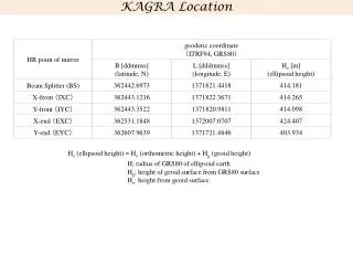
Location of Four Mirror Cryostats in Kamioka Mine Constructed at the position of 1 km in depth. Mozumi-End Atotsu-End X-Front Room Y-Front Room Mirror a cryostat Connection Port to SAS L=5 m Gate valve L=5 m Gate valve Vacuum duct800 with radiation shield Vacuum duct800 with radiation shield
Structure of KAGRA Cryostat Stainless steel t=20mm Diameter 2.4 m Height ~4.3 m M ~ 12 ton Cold Mass: 8K shield ~455 kg 80 K shield ~590 kg Seismic Attenuation System (SAS) Cryogenic Payload 4.3 m Sapphire Mirror (-alumina crystal) View Ports Radiation Shields Duct Shield Main Laser Beam Cryocoolers Pulse tube, 60Hz 0.9 W at 4K (2nd) 36 W at 50K (1st) Four Cryocooler Units 2.6m S.Koike
2014 PAB Recommendation 18: The basic performance test/inspection, especially leak tests, should be completed before the beam tube installation. The current plan to do this by the coming January should be kept. Suzuki: The leak test of Cryostat in X-end was performed in January 2015. The top flange of the cryostat with a diameter of 2400 mm was fastened using a metal gasket. This part will never be able to open after constructing a clean booth. No excess leak was found on the background level of 1x10^-12 Pa*m^3 /sec. This result satisfied the requirement of KAGRA vacuum system that specify a leak less than 1x10^-10 Pa*m^3 /sec. Assembling other three cryostats in Y-end and XY-front is in progress. Leak test for those cryostats will finish until April 2015. 2015 External Review Recommendation: Vibration measurements with the cryo-cooler in operation should be repeated at appropriate locations corresponding to the final design configuration, to more accurately assess vibration transfer. If the resulting spectrum remains as serious as was presented from the preliminary measurements shown, more understanding and development of mitigation techniques will be necessary. This may have radical impact on the cryogenic plant and/or payload designs. Comment: All the cryocoolers have been delivered to the KAGRA site, but cryocoolers have not all been integrated with the end cryostats. Although the cooling time for the radiation shield and vibration levels at the shield have been measured at Toshiba facility, it is highly desirable to demonstrate the cooling and vibration levels inside the real cryostat at the KAGRA site as soon as possible to alleviate remaining uncertainties about the cryogenic operation of KAGRA. If isolation of cryocooler vibration should be insufficient, it could render the vibration isolation achieved by super-attenuators useless. Recommendation: The cryocoolers should be integrated with at least one end cryostat and vibration isolation system, so that both cooling and vibration isolation can be tested as soon as possible. This will also afford VIS and CRY teams an opportunity to work together on integration of their systems.