Download

1 / 66
660 likes | 684 Vues
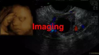
Fluoroscopy is a real-time imaging technique used to visualize organ motion, insert stents, catheterize small blood vessels, and monitor the effects of contrast agents. This technology has evolved from early fluoroscopes to the more advanced image intensifier design, which provides brighter images with reduced radiation exposure. The use of cesium iodide input phosphor and a photo cathode improves image quality and resolution. The electron beam is focused and accelerated by electrostatic focusing cups and an accelerating anode, respectively. The output phosphor emits light photons that carry the fluoroscopic images to the observer.

E N D
Fluoroscopy REAL TIME IMAGING Purpose To visualize, in real time: organ motion ingested or injected contrast agents insert stents cathetarize small blood vessels
X-rays were discovered because of there ability to cause fluorescence . The first x-ray image of human part was observed fluoroscopically-Dr. Glasser.
THE FLUOROSCOPE First generation fluoroscopes consisted of an x-ray tube, an x-ray table and a fluoroscopic screen. A sheet of lead glass covered the screen, so that radiologist could stare directly into the screen with out having the x-ray beam strike his eyes.
The fluorescent material used in screen was copper activated zinc cadmium sulfide that emitted light in yellow-green spectrum. Screen fluoroscence was very faint so, the examination was carried out in a dark room by the radiologist who had to adapt his eyes by wearing red goggles for 20-30 mins prior to the examination technique is now obsolete & gone.
Photograph shows an early (1933) fluoroscopic system in use before the development of image intensification. An actual fluoroscopic examination with this device would have occurred in a darkened room.
IMAGE INTENSIFIERDESIGN Image intensifier was discovered in 1950s-to produce an image bright enough to allow cone vision without giving the pt an excess radiation exposure. The tube itself is an evacuated glass envelope ,a vacuum tube containing- 1.input phosphor and photocathode . 2.electrostatic focusing lens. 3.accelerating anode. 4.out put phosphor.
After an x-ray beam passes the pt it enters the image intensifier tube the input fluorescent screen absorbs x-ray photons and converts their energy into light photons. The light photons strike the photo cathode, causing it to emit photoelectrons these electrons are immediately drawn away from the photocathode by the high potential difference betn it &the accelerating anode. As the electrons flow from the cathode towards the anode, they are focused by an electrostatic lens which guides them to the output fluorescent screen without distorting their geometric configuration.
The electrons strike the output screen, which emits the light photons that carry the fluoroscopic images to the eye of the observer. • In intensifier tube, the image is first carried by the x-ray photons, then by the light photons, next by the electrons &finally by the light photons.
INPUT PHOSPHOR & PHOTO CATHODE: The input fluorescent screen in image intensifiers is cesium iodide (CsI). (older intensifier- silver activated zinc cadmium sulfide). CsI is deposited on a thin aluminum substrate by a process called “vapor deposition”. an interesting & useful characteristic of CsI is that during the deposition process the crystals of CsI grow in tiny needles perpendicular to the substrate. There by reducing scattering.
INPUT PHOSPHOR & PHOTO CATHODE: • Image quality is dramatically better with CSI input screen than it was with zinc cadmium sulfide screens. • Three physical characteristics of CsI make it superior. 1. vertical orientation of the crystals. 2. A greater packing density & 3. A more favorable effective atomic number. • Phosphor thickness have been reduced comparably from app. 0.3mm with Zn-Cd su to 0.1mm with CsI. The principal advantage of thinner phosphor layer combined with needle shaped crystals is improved resolution.
PHOTO CATHODE: The photo cathode is a photoemissive metal (commonly a combination of antimony & cesium compounds). The photo cathode is applied directly to the CsI input phosphor.
ELECTROSTATIC FOCUSING CUP: series positively charged electrodes that are usually plated on to the inside surface of the glass envelope. These electrodes focus the electron beam as it flows from the photocathode toward the output phosphor. Electron focusing inverts & reverses the image which is called “point inversion” because all the electrons pass through a common focal point on their way to output phosphor.
The input phosphor is curved to ensure that electrons emitted at the peripheral regions of the photocathode travel the same distance as those emitted from the central region. The image on the output phosphor is reduced in size ,which is one of the principle reasons why it is brighter.
ACCELERATING ANODE : The anode is located in the neck of the image tube. Its function is to accelerate electrons emitted from the photocathode towards the output screen. the anode has a +ve potential of 25 to 35 kvrelative to the photocathode, so it accelerates electrons to a tremendous velocity.
OUTPUT PHOSPHOR: silver activated zn-cd sulfide, the same used in Ist generation input phosphor. Crystal size and layer thickness are reduced to maintain resolution in the minified image. A thin layer of aluminum is plated onto the fluorescent screen prevent light from moving retrograde through the tube & activating the photocathode.
The glass tube of the image intensifier is 2 to 4mm thick & enclosed in a lead lined metal container protects the operator from stray radiation. The output phosphor image is viewed either directly through a series of lenses and mirrors or indirectly through closed circuit TV.
BRIGHTNESS GAIN: Two methods are used to evaluate the brightness gain of image intensifiers. First compares the luminance of an intensifier output screen to that of a Patterson type B2 fluoroscopy screen when both are exposed to same quantity of radiation. The brightness gain is the ratio of the two illuminations. Brightness gain=intensifier luminance/Patterson b-2 lumin.
Another way is “conversion factor”. The method is accurate & reproducible. Conversion factor =cd/m2 by mR/sec The brightness gain tends to deteriorate as the image intensifier ages. ie the pt dose with an older image intensifier tends to be higher than with a new intensifier of the same type. The brightness gain of an II comes from 2 completely unrelated sources called minification gain &flux gain.
MINIFICATION GAIN: The brightness gain from minification is produced by a reduction in image size. Depends on the relative areas of input &output screens. coz the size of the intensifier is usually indicated by its diameter. MG=(d1/d0)2.d1=diameter of input screen,d0=diameter of output screen. Most II have an input screen from 5 to9 in. & an output screen of app 1 inch diameter.
Theoretically minification can be increased indefinitely but as the minification is increased the image becomes smaller.-disadvantage. Hence image has to be magnified and viewed which will result in reduce brightness & precipitous drop in resolution.
FLUX GAIN: FLUX gain increases the brightness of the fluoroscopic image by a factor of app 50. The total brightness of an II is product of minification & flux gain: ie Brightness gain =minification gain x flux gain.
MULTIPLE-FIELD IMAGE INTENSIFIERS Dual field or triple field II attempt to resolve the conflicts btn image size & quality. They can be operated in several modes, including the 4.5in, a 6in, or a 9in mode. the 9in mode is used to view large anatomic areas. When size is unimportant the 4.5in or 6in mode is used coz of better resultant image quality. Field size is changed by a simple electronic principle: the higher the voltage on the electrostatic focusing lens, the more the electron beam is focused.
This figure shows this principle applied to a dual field II. • In the 9in mode, the electrostatic focusing voltage is decreased. the electrons focus to a point or cross, close to the output phosphor & the final image is actually smaller than the phosphor. • In 6in mode the electrostatic focusing voltage is increased & the electrons focus farther away from the output phosphor. after the electrons cross they diverge, so the image on the output phosphor is larger than in the 9in mode.
Optical coupling Optical system transmits the output of the image intensifier to the light sensitive area of the video camera The optical distributor include beam-splitting mirror, which directs a portion of the light from the image intensifier output window to an accessory device for image recording and passes the remainder to the video camera. Two lenses are mounted in tandem The II and the vidicon are placed at the focal planes of the two lenses
Closed-circuit Television System used to view the image intensifier output image Consists of 1)Television camera 2) Camera control unit 3) Monitor The television system allows for real-time viewing of the fluoroscopic image by several people at once from one monitor or multiple monitors
Television Camera Tube Output phosphor is directly coupled to a TV camera tube Plumbicon Vidicon CCD
The basic video camera consists of 1) vacuum tube cylinder (approximately 2.5 cm in diameter) surrounded by electromagnetic focusing coils ,2 pairs of electrostatic deflecting coils 2) photoconductive target 3) a scanning electron beam Target assembly: a) Glass plate assembly b) signal plate c) Target
Target Functionally most important in tube Thin film of photoconductive material, antimony sulfide suspended as globules in mica matrix. The optical coupling lens focuses the image intensifier output image onto the target, forming a charge image within the photoconductive layer
This latent image is read out by the electron beam, which scans across the target in a series of horizontal raster lines. As the scanning electron beam moves across the target, a current signal is produced that represents the two-dimensional image as a continuous series of raster lines with varying voltage levels.
Video signal When globules absorbs light ,photoelectrons are emitted The globule becomes positively charged The electron beam scans the electrical image stored on the target & fills in the holes left by the emitted photoelectrons, discharging the tiny globular capacitors
When the electrons in beam neutralize the positive charge in the globules , the electrons on the signal plate leave the plate via resistor These moving electrons form a current flowing through a resistor and voltage across the resistor This voltage ,when collected for each neutralized globule, constitutes the video signal
CCD Same resolution as vidicon No electron beam needed for reading Stores negative charge PLUMBICON- PbO is the photoconductive material
Camera control unit Reassembling the pulses to a visible image
Television monitor The video signal produced by the video camera is converted into a visible image by the monitor Contains picture tube & controls for regulating brightness & contrast Picture tube contains- Electron gun control grid anode focusing coil, deflecting coil-control the electron beam synchrony with the camera tube
Control grid-receive video signal from Camera control unit ,uses this signal to regulate the no. of electrons in electron beam Anode –carries higher potential (10,000V) accelerates the electron beam to much higher velocity The electron Strike the fluorescent screen ,emit large number of light photons.
Image Recording Two modes of recording the fluoroscopic image - 1) light image from output phosphor of II recorded on film with a photospot camera or cine camera 2) electrical signal generated by TV camera-includes magnetic tape, magnetic discs & optical discs
DIRECT FILM RECORDING SPOT FILM DEVICES: Fluoroscopic systems designed for gastrointestinal imaging are generally equipped with a spot film device. The spot film device allows exposure of a conventional screen-film cassette in conjunction with fluoroscopic viewing. This rather familiar system, located in front of the image intensifier, accepts the screen-film cassette and "parks" it out of the way during fluoroscopy Cassettes may be loaded from the front or rear depending on the design of the system.
Standard spot film imaging configurationtypical of gastrointestinal fluoroscopy equipment. The screen-film cassette is parked out of the x-ray field until the spot film trigger is pressed, causing both the cassette and the formatting mask to move into position.
The x-ray field size is also reduced automatically by the collimators at the time of exposure to minimize scattered radiation and patient radiation dose. • Spot film imaging uses essentially the same technology as conventional screen-film radiography. Differences and limitations of spot film imaging compared with general radiography. • One major limitation is the range of film sizes available for spot film imaging. Although some older fluoroscopy equipment is limited to a single size, usually 24 x 24 cm, current equipment allows a range of film sizes to be used, from 20 x 25 cm to 24 x 35 cm. • Spot film devices usually allow more than one image to be obtained on a single film. • Formats typically include one, two, three, four, or six images on a film.
Moving the spot film device closer to the patient reduces the amount of magnification and decreases the patient radiation dose. • A number of factors affect patient doses in spot film imaging. • The source-to-skin distance is shorter in spot film imaging than in general radiography. • Although the automatic exposure control system fixes the exposure to the screen, the shorter source-to-skin distance increases the inverse square reduction in radiation intensity as it passes through the patient. • This increase tends to make the skin entrance exposure higher. • The field size in spot film imaging is generally smaller than that used in general radiography. • This smaller field size reduces scatter and therefore tends to reduce dose. For the same reason, grids used in fluoroscopy generally have a lower grid ratio and therefore a smaller Bucky factor, which also leads to lower dose. • These effects tend to offset each other to a large extent.