09 – Drawing and Blueprint Reading
1.42k likes | 2.43k Vues
09 – Drawing and Blueprint Reading. The intent of this presentation is to present enough information to provide the reader with a fundamental knowledge of drawings and blueprints used within Michelin and to better understand basic system and equipment operations.

09 – Drawing and Blueprint Reading
E N D
Presentation Transcript
The intent of this presentation is to present enough information to provide the reader with a fundamental knowledge of drawings and blueprints used within Michelin and to better understand basic system and equipment operations.
09 Drawing and Blueprint Reading Orthographic viewing In our everyday experience or of, looking at objects, we rarely see their true shape. A rectangular table appears as a parallelogram when we stand at one of its corners to look at it. Circular holes often appear to be oval. The reason for this is that unless we look directly at right angles to a surface, some of the lengths become foreshortened. In the case of the table, one of the diagonals appears to be shorter, and with the circles, one of the diameters. If we are to produce a drawing in its true shape, we must view an object perpendicularly to its surfaces. This is the principle of orthogonal viewing. The word orthogonal means right angled. Let us consider the orthogonal views of the item shown below.
09 – Drawing and Blueprint Reading The oblique view shows a cylinder mounted on a square base. First, looking in direction A, we see a circle for the end of the cylinder. We cannot see any of the curved surface because this is in a line with our sight and is therefore "lost". Next, we see a square of the base, but again the thickness has disappeared. Looking in direction B, we can see a rectangle for the side of the cylinder. No curvature is seen because all distances from the eye are lost and the ends become straight lines equal in length to the diameter, thus only a rectangle is seen. It is this type of viewing which we use in making mechanical drawings.
From the drawing, choose the numbered orthographic view that matches the arrows of the pictoral view. 7 5 13
09 – Drawing and Blueprint Reading Arrangement of the views and their designation The name given to each view depends upon: • The position of the front view - chosen as the most explanatory or descriptive view. • Then giving names to each position according to where the observer must be to look at the corresponding view The arrangement of these views can fall into one of either two major categories: • FIRST ANGLE PROJECTION ( OR EUROPEAN PROJECTION) • THIRD ANGLE PROJECTION (OR AMERICAN-US PROJECTION)
09 – Drawing and Blueprint Reading On the following two exercises match the numbered surfaces of the orthographic views to the lettered surfaces of the pictorial view. 1 9 16 15 11 2 8 4 17 10 7 5 13 6 12
13 3 10 5 8 16 18 6 17 15 4 7 2 14 11 12 1 9
09 – Drawing and Blueprint Reading Number of views necessary to define an object: In most cases, two views, if chosen judiciously, are enough to represent a single part. (Always choose the views with the least hidden lines). Let’s take, for example, the following part:
09 – Drawing and Blueprint Reading To define it entirely, the five dimensions indicated on the above pictorial are necessary. On the drawing in orthographic projection below, the same dimensions should also be indicated. The views are shown in European projection. Those dimensions appear on the front and right side views above
09 – Drawing and Blueprint Reading The dimensions are well indicated, but the part is not well defined in shape. From the preceding two views, we can imagine the cut-away in the corner of the part being of several different shapes, as shown below, but still corresponding to the same projections. If the top (or plan) view is used with the front view as indicated, any possible doubt is cleared up.
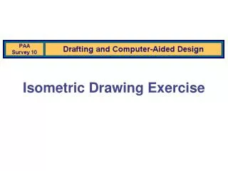
Spatial viewing exercises INSTRUCTIONS: To the right is an isometric view of a machined part with 6 dots placed at various locations. The object is to determine the linear measurement of the thickness of the material behind each dot. In the event a slot or other air space is directly behind the dot, simply deduct the amount of air space as was done on point 3 of the example. 1) 70 (100-30) 2) 100 3) 13 (35-22) 4) 27 (35-8) 5 ) 8 6) 30 (50-20)
75 75 50 15 40 30
80 40 50 30 40
75 55 50 30 40 30 15
15 40 21 33 7
50 55 40 12 45 25
50 30 50 38 12 75 34
62 68 60 46 21 18 37 58
29 51 51 41 11 16 25 0 12 15 26
35 73 30 0 30 16 46 56 19
125 22 75 43 35 29 23
09 – Drawing and Blueprint Reading Sketching
09 – Drawing and Blueprint Reading Interpretation of the graphics language as shown on mechanical blueprints Since time immemorial, man has always tried to transmit his thoughts and to express them through drawings to ensure their endurance. The first writing techniques, such as the hieroglyphics of the Egyptians, were drawings or graphs. Thus, a graph is the expression of a concept through the use of lines made on a surface. This definition fits perfectly the representation of an object via a drawing. Finally, this language, which will be understood by people speaking different languages, is used universally to communicate ideas and feelings. Drawing has greatly evolved over the centuries and, today, falls under two broad categories, each having its own purpose: artistic drawing, which expresses figurative or non-figurative ideas for cultural or commercial ends; industrial drawing which, whatever the industrial sector, transmits technical or practical ideas. Many people have to read blueprints. Even in everyday life, a grasp of mechanical drawing will prove very useful to understand the plans of a house, the assembly, maintenance and instructions pertaining to the operation of many manufactured products, as well as assembly and operation plans and instructions of various appliances.
09 – Drawing and Blueprint Reading What is mechanical drawing? On many occasions in our everyday life, we find it necessary to exchange information in some sort of graphical form. If we can express complex ideas through simple drawings, then our drawings will allow a much easier transmission and reception of the information that we want to communicate. This is why we use, for example, a road map to find our way in an unknown area. Different types of communication aids, characterized by their use of graphics, are used in many different areas. Mechanical drawing or technical drawing sometimes even called industrial drawing, is one type of communication aid. It is a real language which is used as an important means of communication in industrial life. As a matter of fact, it is the communication tool most used by the craftsmen in industry.
09 – Drawing and Blueprint Reading Role of Mechanical Drawing—Everyday Life The usefulness of mechanical drawing is very obvious. A knowledge of drawing, or blueprint reading, makes it easier for us to understand other types of representations: • Map reading, diagrams, schematics, etc. • To make simple sketches (accident reports, where to install a piece of furniture). • Allows us to better understand the drawings and schematics which we see in current magazines. But beyond these practical uses, making drawings and blueprints also has an educational value. It develops an artistic sense, improves our sense of observation, and develops precision use of language.
09 – Drawing and Blueprint Reading Role of Mechanical Drawing—Industrial Life Mechanical drawing is an intermediary between man and: • the item to be made (to go from an idea to a real thing) • his work (a means of achieving the work he does) • those who participate in his work (a means of communicating between all the people on the work team). For example, mechanical drawing: • Allows us to know the function, the overall dimensions, and the way to install a machine. • Shows us the correct position of the different parts and how to place them. • Gives precise information to the machinists in order for the parts to be made. • Helps the designer to preview his design. These are the reasons why you have to know how to read and interpret mechanical drawings, or blueprints, if you work in industry. The drawing office personnel draftsmen, designers, etc.) must know even more technical information to prepare the documents.
09 – Drawing and Blueprint Reading Different Kinds of Drawings Because it is an intermediary between the persons who create a machine and the persons who make it, a drawing can take different forms according to its role and the people who will use it. Drawings for fabrication with standardized symbols--for mechanical, welding, buildings, electrical construction, etc. Sketches illustrating an idea, technical principle, description. Schematic explaining the operation of machines. Electrical, hydraulic, and pneumatic circuits. Curves, calculations of graphical statistics. Control instrument diagrams. Pictorial drawings for better visualization.
09 – Drawing and Blueprint Reading In the early years of manufacturing, drawings were scaled by the workman to obtain sizes. It was up to the workman to make the parts fit together, and work properly, by trying the mating parts together as he made them. The need for interchangeability of parts requires exact methods of size description. Today, drawings must be dimensioned so that parts made in different plants will fit together properly. The drawing must contain all the necessary information to make the part without having to refer to any of the mating parts. The workman should not have to scale or assume any dimension to make the part.
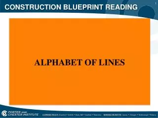
09 – Drawing and Blueprint Reading Lines An extension line is a fine (0.18mm) line that extends from a point on a drawing. A dimension line is a fine (0. 18mm) line that meets the extension line, is parallel to the dimensioned part, and has an arrowhead at each end, in most cases.