Potentiostat Basics
Potentiostat Basics. The Electrochemical Interface. A potentiostat is an instrument which measures the current / voltage characteristics of an electrochemical (electrode/solution) interface. =. “Electrode”. Why does a potentiostat have to be so #$@! complicated!?.


Potentiostat Basics
E N D
Presentation Transcript
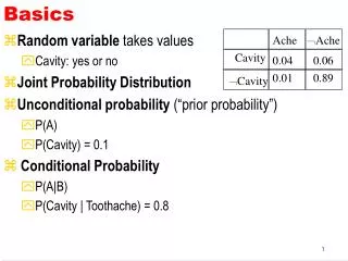
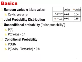
The Electrochemical Interface • A potentiostat is an instrument which measures the current / voltage characteristics of an electrochemical (electrode/solution) interface. = “Electrode”
Why does a potentiostat have to be so #$@! complicated!? Why can’t a potentiostat be as simple and inexpensive as an ohmmeter?
Electrodes • A potentiostat works with electrodes immersed in a conductive medium. • Working Electrode A sample of the corroding metal being measured. • Reference Electrode An voltage-sensing electrode with a constant electrochemical potential. • Counter Electrode A current-carrying electrode that completes the cell circuit.
Reference Electrode • The reference electrode impedance must be kept low • High impedance electrodes pick up noise. • High impedance electrodes can cause oscillation • To lower the impedance • Use large junction reference electrodes • Replace isolation frits regularly • Avoid narrow Luggin Capillaries
Potentiostat Definition • Potentiostat • An electronic device that controls and measures the voltage difference between a working electrode and a reference electrode. • It measures the current flow between the working and counter electrodes.
Galvanostat Definition • Galvanostat • An electronic device that controls and measures the current flow between a working and a counter electrode. • It measures the potential between the working electrode and a reference electrode.
ZRA Definition • Zero Resistance Ammeter (ZRA) • An electronic device that controls the voltage between two electrodes (usually at 0 V), and measures the current flow between them. • A ZRA may also measure the potential of one of the electrodes versus a reference electrode. • ZRA mode is used for electrochemical noise and galvanic corrosion measurements.
Electrometer Characteristics • The Ideal: • Perfectly Accurate • Infinite Input Impedance • Zero Input Capacitance • Infinitely fast • Infinite common mode rejection (crosstalk) • The Real: (Series G 300) • DC Accuracy ±0.3% of reading 1 mV • Input Current < 10 pA • Input Resistance > 1 TW • Input Capacitance < 5 pF • Bandwidth (-3 dB) > 4 MHz • CMMR > 80 dB @DC to 3 Hz > 60 dB @ 100 kHz 3/28/2005 RSR
I/E Converter Characteristics • Cell current is measured by passing the current through a known resistance, Rm. • Cell currents vary widely, so an I/E Converter needs a wide range of resistor values (typically 1 W to 10 MW). • For the Series G 300: • Full-Scale Ranges 3 nA to 300 mA in decades • DC Accuracy 0.3% of range 50 pA • Bandwidth (-3 dB) > 500 kHz (300 mA to 300 mA) 3/28/2005 RSR
Control Amplifier • The control amplifier is a high power device. • Series G 300Series G 750Reference 600 • Maximum voltage 20 volts 12 V 22 V • Maximum current 300 mA 750 mA 600 mA • Modern potentiostats should be protected from damage due to misconnection of this output to any other cell connection. 3/28/2005 RSR
Potentiostat Accuracy Contour Map • Every point represents a frequency and an impedance. • Plot iso-accuracy lines. Gain accuracy and phase accuracy can be plotted separately.
Trouble-Shooting a Gamry Potentiostat • Calibrate the instrument with an external 2000 ohm resistor (UDC3). The unit should calibrate with no errors. This test catches at least 75% of all possible problems. If the instrument fails to calibrate properly, examine the Calibration Results <S/N> file. • Run a Polarization Resistance scan on the 2000 ohm calibration resistor. Compare the actual current to the calculated current using Ohm’s Law (E = iR). • A resistor has an Eoc of zero, which isn’t realistic. Attach a battery in series with the resistor for an “off-zero Eoc” dummy cell. Connect the Working to the resistor, the Counter between the resistor and battery, and Reference to the battery. Run a Polarization Resistance and verify correct Eoc. • Run an Electrochemical Impedance Spectroscopy (EIS) test on the Universal Dummy Cell. Fit the curve to the Randles model. Resistors should fit within 1.5% of nominal, cap within 6%. These tolerances are wide because of the dummy cell component tolerances (1% for the resistors and 5% for the cap). • Run an EIS curve on a capacitor (220 pF) from 100 kHz to 50 uHz. Look for phase breaks in the Bode plot. Phase should be 90 +/ 2 degrees until Z is above 109 ohms. Analyze the resulting curve by fitting to a parallel RC model. Cap should be within 5% and resistor should be greater than 100 GOhm (Series G) or 1 TOhm (Reference 600). This procedure tests all current ranges, noise levels, leakage currents, etc. • Unstable voltage oscillations are often caused by bad reference electrodes. Use 2 electrode configuration to check. • When in doubt, call Gamry!
Potentiostats and the Lunatic Fringe! • The use of potentiostats is limited only by your imagination. Several real applications are: • Electrochemical experiments in molten salts at 450º C. • Corrosion experiments in an autoclave at 300° C. • Apply a constant current on one side of a metal electrode and a constant potential and measure the current on the other side of the electrode. • Potentiostatically control seven independent working electrodes in one solution with one reference electrode and one counter electrode.