Download

1 / 2
20 likes | 37 Vues
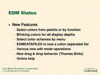
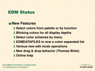
The aircraft Engine Data Manager 760 (EDM 760), essentially consists of two parts u2013 the display and the probes. While the display goes into the cockpit (obviously), the probes are attached to various parts of Aircraft Engine monitor (or fuselage) depending on the nature of the probe. Each of these probes is in turn connected to the display unit via wires.<br><br>The EDM 760 uses slim line, fast-response probes that provide near instantaneous data to the display unit.<br><br>INSTALLING THE INDICATOR<br><br>Open the package and retrieve the steel template for the display unit. This template should be used as a guide for drilling two buttonholes in the instrument panel. The EDM 760 requires a standard 3.125" instrument hole. You do not have to worry about any configuration. The moment the pilot switches on the engine, the instrument configures itself automatically for twin 4 or 6-cylinder, 14/28-volt aircraft. The instrument is 7.5u201d deep (without connectors) and is 3.20 square behind the panel.<br><br>EXHAUST GAS TEMPERATURE PROBE (EGT)<br><br>The JPI EDM 740 contains the Model M-111 probe. This will fit any existing holes in the exhaust stack in any engine having the diameter of 1/8" to 1/4". If you do not find any pre-existing holes, then, please drill a 1/8" diameter hole and ream to fit. Each probe should be mounted at a uniform distance from the exhaust stack flange (2 to 4 inches is recommended). <br><br>For accurate temperature data, ensure that the tip of the probe is in the centre of the exhaust stream. When sure that the probe is in the right place, tighten the stainless-steel clamp to a torque of 45 in/Lbs. Cut off the excess strap close to the screw.<br><br>TURBINE INLET TEMPERATURE PROBE (TIT)<br><br>The EDM 760 Kit will contain the P/N M-111-T TIT probe that has a special clamp. The TIT probe is placed in the exhaust stack accumulator to a maximum depth of 1/2 inch and approximately four (4) inches from the Turbine inlet. The TIT probe will appear as the seventh column u201cT u201cof the display unit and u201c1650 TITu201d will be displayed when the dot is in place over it.<br><br>WIRING (12 / 24 volt)<br><br>Your EDM-760 is suitable for both 14 and 28-volt systems. Use the 15-pin connector to connect to the power lead. Ideally, you should insert a 2-amp in-line fuse connected to the avionics power buss. Once this is done, the pilot can use the avionics master switch to turn on/off the instrument during engine start-up. If there is no such switch, it might be worth your while and money to have one installed. The EDM-760 will self-test on start-up (takes 10-seconds).<br><br>Visit here for more information : https://www.jpinstruments.com/shop/edm-760/

E N D
The aircraft Engine Data Manager 760 (EDM 760), essentially consists of two parts – the display and the probes. While the display goes into the cockpit (obviously), the probes are attached to various parts of Aircraft Engine monitor (or fuselage) depending on the nature of the probe. Each of these probes is in turn connected to the display unit via wires. The EDM 760 uses slim line, fast-response probes that provide near instantaneous data to the display unit. INSTALLING THE INDICATOR Open the package and retrieve the steel template for the display unit. This template should be used as a guide for drilling two buttonholes instrument panel. The EDM 760 requires a standard 3.125" instrument hole. You do not have to worry about any configuration. The moment the pilot switches on the engine, the instrument configures automatically for twin 4 or 6-cylinder, 14/28-volt aircraft. The instrument is 7.5” deep (without connectors) and is 3.20 square behind the panel. in the itself EXHAUST GAS TEMPERATURE PROBE (EGT) The JPI EDM 740 contains the Model M-111 probe. This will fit any existing holes in the exhaust stack in any engine having the diameter of 1/8" to 1/4". If you do not find any pre-existing holes, then, please drill a 1/8" diameter hole and ream to fit. Each
probe should be mounted at a uniform distance from the exhaust stack flange (2 to 4 inches is recommended). For accurate temperature data, ensure that the tip of the probe is in the centre of the exhaust stream. When sure that the probe is in the right place, tighten the stainless- steel clamp to a torque of 45 in/Lbs. Cut off the excess strap close to the screw. TURBINE INLET TEMPERATURE PROBE (TIT) The EDM 760 Kit will contain the P/N M-111-T TIT probe that has a special clamp. The TIT probe is placed in the exhaust stack accumulator to a maximum depth of 1/2 inch and approximately four (4) inches from the Turbine inlet. The TIT probe will appear as the seventh column “T “of the display unit and “1650 TIT” will be displayed when the dot is in place over it. WIRING (12 / 24 volt) Your EDM-760 is suitable for both 14 and 28-volt systems. Use the 15-pin connector to connect to the power lead. Ideally, you should insert a 2-amp in-line fuse connected to the avionics power buss. Once this is done, the pilot can use the avionics master switch to turn on/off the instrument during engine start-up. If there is no such switch, it might be worth your while and money to have one installed. The EDM-760 will self-test on start-up (takes 10-seconds). Visit here for more information : https://www.jpinstruments.com/shop/edm-760/ JPI Sales: 1-800-345-4574 714-557-3805 FAX: 714-557-9840 sales@jpinstruments.com JPI Technical Support: 1-800-345-4574 714-557-3805 support@jpinstruments.com J.P. Instruments Inc: 3185-B Airway Ave Costa Mesa, CA 92626