Download
1 / 40
410 likes | 442 Vues
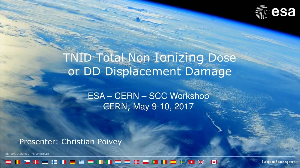
TNID Total Non Ionizing Dose or DD Displacement Damage. ESA – CERN – SCC Workshop CERN, May 9-10, 2017. Presenter: Christian Poivey. Electrons Protons Heavier ions. Displacement Damage - Introduction. (e-). p+. p+. p+. e-. Ion. Trapped charges. Oxide.

E N D
TNID Total Non Ionizing Doseor DD Displacement Damage ESA – CERN – SCC Workshop CERN, May 9-10, 2017 Presenter: Christian Poivey
Electrons Protons Heavier ions Displacement Damage - Introduction (e-) p+ p+ p+ e- Ion Trapped charges Oxide + + + + + + + + + + - - + - + - + - - - Oxide Oxide Displacement Damage Interstitials • + - + • - + + - • + - - + • + + + Silicon Interface traps Ionisation Silicon Silicon Vacancies DD is a result of particle Energy deposition in the bulk of semiconductors (Si, GaAs,…) Only a very small fraction of Energy deposition goes into Displacement Damage Ion 2nd Total Ionising Dose Single Event Effects
Displacement Damage - Mechanism Vacancies and interstitials migrate, either recombine ( ~90%) or migrate and form stable defects (Frenkel pair)
Displacement damage - Mechanism • Energy of recoils (PKA spectrum) is determined by the collision kinematics • electrons produce low energy PKAs • low energy protons (< 10 MeV in Si, higher in GaAs) : Coulomb (Rutherford) scattering dominates • low energy PKAs • neutrons and higher energy protons - nuclear elastic scattering and nuclear reactions (inelastic scattering) • flat PKA spectrum • above ~ 20 MeV in silicon, inelastic collisions tend to dominate isolated (point) defects E cascades & multiple cascades E
Displacement damage - Mechanism 6 -10 MeV >20 MeV (Wood 1981) Defect Cascades 1 – 2 keV 10-20keV As the energy of the proton increases the energy transferred from the colliding proton with a Si atom occurs via nuclear elastic interaction. More energy is transferred to the recoil atom which again can go on and create additional recoil atoms and hence defect cascades. With even higher proton energies the probability of nuclear interaction increases. Many sub cascades may be generated.
Cascades - Examples • 50 keV PKA is typical of what can be produced by a 1MeV neutron or high energy proton • Threshold displacement energy in Si: 21 eV (After Johnston, NSREC short course 2000)
Non Ionizing Energy Loss (NIEL) • Final concentration of defects depends only on NIEL (total energy that goes into displacements, about 0.1% of total energy loss) and not on the type an initial energy of the particle • Number of displacements (I-V pairs) is proportional to PKA energy • Kinchin-Pease: N=T/2TD; T: PKA energy; TD: threshold energy to create a Frenkel pair) • In cascade regime the nature of the damage does not change with particle energy- just get more cascades • nature of damage independent of PKA energy
Non Ionizing Energy Loss (NIEL) • Assume underlying electrical effect proportional to defect concentration(Shockley Read Hall theory) • Damage constant depends on device and parameter measured damage = kdamage x displacement damage dose
Terms and Units • NIEL(displacement kerma = Kinetic Energy Released to MAtter) • keVcm2/g or MeVcm2/g • Displacement Damage Dose DDD • (keV/g or MeV/g) • Displacement Damage Equivalent Fluence DDEF (mono-energetic beam) • e.g. 10 MeV protons/cm2 or 1 MeV neutrons/cm2
NIEL deviations: GaAs devices • (Walters, TNS 2001) But NIEL scaling is a good first approximation. It removes most of the energy (and particle) dependence. Without NIEL, testing/prediction would be much more complicated. NIEL tables are available in OMERE for any kind of material(NEMO tool). See also http://www.sr-niel.org/
Device Effects – Lifetime Damage • Minority carrier lifetime • affects bipolar ICs (e.g. wide base regions in lateral & substrate pnp transistors, >3 1010 50 MeV p/cm2) • reduces detector responsivity (decrease in diffusion length, (Dt)1/2) • reduces efficiency of solar cells • reduces light output of LEDs (non-radiative recombination) • threshold current increase in laser diodes • reduction of current transfer ratio (CTR) in optocouplers • LED, phototransistor and coupling medium can be affected • sensitive devices can degrade at 1010 - 1011 50 MeV protons/cm2
Device Effects – Majority Carrier Removal • approximate carrier removal rates • effect depends on doping (and whether n- or p- type) • for doping of 1015/cm3, carrier removal starts to be important for 50 MeV proton fluences ~ 1012 p/cm2 • but lightly doped structures can degrade at lower fluence (e.g. i-region of a p-i-n diode: due to leakage currents - 1010 p/cm2) • but p-i-n diodes harder than conventional diodes since not sensitive to lifetime effects - collection by drift rather than diffusion • type inversion (n- to p-type) in detectors& increase in depletion voltage • carrier removal important for solar cellsat high fluence (After Johnston NSREC2000 short course notes)
Device Effects –Example – Operational Amplifier LM124, input bias current Comparison of TID degradation with Co-60 only and different combinations of proton and Co-60 irradiation (RUAG Sweden test data for an ESA study, 2011)
Device Effects –Example – Operational Amplifier LM124, input bias current Comparison of TID degradation with Co-60 (HDR and LDR) irradiation and high-energy electron irradiation (LIP test data for an ESA study, 2016)
Device Effects – Example - Optocoupler 66168, CTR (Astrium test data for an ESA study, 2008)
Device Effects – Example - Optocoupler • NIEL equivalence • CTR60%@60MeV = CTR60%@15MeV *NIEL15/NIEL60 • - CTR 60%@15 MeV ~ 7E10 p/cm2 • NIEL 15MeV protons (AsGa): 8.54E-3 MeVcm2/mg • NIEL 60 MeV protons (AsGa)= 4.03E-3 MeVcm2/mg • CTR60%@60MeV ~ 1.48E11 #/cm2 • Actual value (from data) ~ 2E11 p/cm2 • TID deposited by 7E10 p/cm2 of 15 MeV protons ~ 21.4 Krad • TID deposited by 1.5E11 p/cm2 of 60 MeV protons ~ 16 krad
Device Effects – Example – Solar Cells • L change: degradation of minority carrierdiffusion length • Rb change: increase in base layer serie resistance Rb due to carrier removal • W change: depletion layer broadening • (M. Yamaguchi, IEEE Trans. Elec. Dev.,1999)
Device Effects – Example – CCDs • Dark image after irradiation with protons • Increase of dark current (overall) • Hot pixels • CTE degradation • Sensor degradation is a significant • Constraint for payloads and star trackers
Device Effects – Example – CCDs Dark Current histogram on CCD TH7890 Irradiated with 9.5 and 60 MeV protons CMOS Image sensors (CIS) show the same behavior Number of hot pixels is reduced at low temperature Hot pixels can be eliminated by software treatment of images. They are a big Issue for star trackers
Device Effects – Example – CCDs PLATO E2V CCD270, Image acquired while Illuminated by Fe55 X-ray source CTI degradation is a big issue for payloads, imposes stringent requirements on pointing accuracy on PLATO (After Prod’homme ESWW2016)
Device Effects – Example – CCDs A sample of 4 CCD pixels showingRandom Telegraph Signal (RTS)behaviour at 23°C Similar RTS behavior is seen inCMOS Image Sensors RTS disappears at low temperature
Bibliography • Gordon Hopkinson, “Radiation Engineering Methods for Space Applications, part 3B: Radiation Effects and Analysis, Displacement Damage”, RADECS 2003 short course notes. • J. Srour, “Review of displacement damage effects in silicon devices,” IEEE Trans. Nucl. Sci., vol. 50, n° 3, pp. 653–670, June 2003. • J Srour, “Displacement Damage effects in devices” NSREC 2013 short course notes. • A.H. Johnston, “Radiation Effects in Optoelectronic Devices,” IEEE Trans. Nucl. Sci., Vol. 60, n° 3, June 2013.
Initial Measurement Irradiation energy / fluence Interim Measurement Annealing application dependant Final Measurement Principle 1.20 Mitel 3C91C (device has no coupling medium) 5mA drive Vce=5V 1.00 #20 initial CTR=98 #29 initial CTR=81 0.80 #49 initial CTR=54 0.60 CTR0/CTR 0.40 0.20 0.00 0 2x10¹⁰ 4x10¹⁰ 6x10¹⁰ 8x10¹⁰ 1x10¹¹ Fluence (32 MeV protons/cm2) CTR: Charge Transfer Ratio (Ioutput/Iinput) (After R. Reed, IEEE TNS vol 48-6, 2001)
DD Test Standards • There is no test standard • Effects are application specific (depend on operating conditions) • Annealing effects (particularly LEDs, laser diodes, optocouplers) • Complex degradation modes ( particularly detector arrays) • Some US MIL and ASTM standards are useful for neutron testing • MIL-STD-883, method 1017, neutron irradiation • F1190-99 Standard guide for neutron irradiation of unbiased electronic components • E798-96 Standard practice for conducting irradiations at accelerator based sources • F980M-96 Standard guide for measurement of rapid annealing of neutron-induced displacement damage in silicon semiconductor devices • Test programme will need to be tailored to requirements
Choice of Particle Type and Energy • If particle type can be representative of the environment then less reliance on NIEL scaling • Protons for most space environment • Electrons or low energy protons for solar cells • Protons give both DD and TID - may need to separate the effects, but usually not so bad since: • CCDs and detectors arrays can usually separate DD and TID effects • LEDs (lens), optocouplers TID effects relatively small • Photodiodes, laser diodes TID effects negligible, unless high dose • Can do proton plus separate Co-60 test (if needed) • Or else can use neutrons for DD plus separate Co-60 test • Care needed to make sure NIEL scaling is valid • Some neutron facilities also give gammas • Neutron facilities often provide a spectrum • Dosimetry may be difficult
Choice of Particle Type and Energy • Protons can be used for both DD & TID, however: • Bias dependence • DD usually is not bias dependent, TID isbias dependent • would have to do a biased proton irradiation, may anyway for photonics (to simulate annealing) but can be difficult for detector arrays • TID is sensitive to dose rate, DD is usually not flux dependent • annealing mechanisms are different - not easy to do accelerated anneals for DD. • but if TID effects are small and dose is reached (or exceeded) during proton testing and biasing is representative, then it may be acceptable to perform just proton testing - but need care of overtest margin if effects are inter-dependent or non-linear with proton fluence
Choice of Particle Type and Energy • If particle energy can be representative of the environment then, again, less reliance on NIEL scaling • choose an energy close to the peak damage energy • For shielded proton environments the main energy of interest is 50 - 60 MeV 800 km – polar orbit
Choice of Particle Type and Energy • 50 - 60 MeV is a good proton test energy • particularly for GaAs devices (NIEL scaling uncertain) • there is a case for using < 30 MeV because of NIEL uncertainties • also good penetration depth (> 10 mm Al), but masking difficult • 10 MeV also a good energy for detector arrays • can mask using thin (1.5 mm) Al plates • comparison with existing data • For solar cells the shielding is reduced and most of the damage comes from low energy protons and electrons • 1-3 MeV electrons and 3 - 10 MeV protons are common • dependence on NIEL is different for electrons and protons, advisable to do separate tests • Always ideal to test at several energies - but not always practical (e.g. funding issues)
Number of devices/fluence steps/flux • Number of test samples needs to be sufficient to cover the number of fluence steps, bias conditions and annealing tests • number of irradiation steps depends on whether a general evaluation or specific for a project • for imager arrays can reduce by masking the device into several fluence regions • for projects, fluence should be derived from environment document (including margins). • some device types show significant device-to-device variations so need to increase the number of devices (e.g. to ~10) to get good statistics • e.g. LEDs, VCSELs, optocouplers • usually arrange each proton irradiation step to take a few minutes ð particle flux ~ 5 x 10⁸/cm2/s • no evidence for flux rate effects in this regime
Example of masking a CCD 60 MeV Protons 10 MeV protons
Irradiation Bias / Temperature • No evidence for defect creation being bias dependent • for DD can usually irradiate unbiased at room temperature • sometimes irradiate at low temperatures if there is a need • Annealing effects in LEDs, optocouplers, laser diodes depends on operation (injection current) • can irradiate unbiased and do a separate annealing test LED (After Johnston, IEEE TNS, 2002) Laser Diode
Irradiation Bias - CCDs Dark Signal (After Robbins, 2013)
Bias Annealing - CCDs Anneal at room temperature measurements, dark signal unbiased clocked (After Robbins, 2013)
European Test Facilities - Protons • Paul Scherrer Institute, Villigen, Switzerlandhttp://pif.web.psi.ch/ • Proton beam line PIF • Initial proton energies: 230, 200, 150, 100 and 74 MeV. • Energies available with PIF degrader: quasi continuously from 6 MeV up to 230 MeV • Energy straggling for an initial energy of 74 MeV • FWHM=2.4 MeV at 42 MeV • FWHM= 5.6 MeV at 13. 3 MeV • Gaussian-form initial beam profiles with standard FWHM=10 cm. • The maximum diameter of the irradiated area: f 9 cm. • Maximum flux at 230 MeV ~ 2E9 protons/sec/cm2 • Neutron background: less than 10-4 neutrons/proton/cm2. • CYCLONE, UniversiteCatholiquede Louvain-la-Neuve, Belgium www.cyc.ucl.ac.be • Proton beam line (LIF) • Initial proton energy: 65 MeV • 10 to 65 MeV using polyethylene degraders • Energy straggling for 14.4 MeV: 1.09 MeV • 10% uniformity over 8 cm diameter • Maximum flux ~2E8 protons/sec/cm2 • neutron fluence/proton fluence 1-5E-4 (depending on neutron energy) • Many others in Netherlands, France,…
Bibliography • NASA Guidelines • “Proton Test Guidelines Development – Lessons Learned,”2002. • RADECS 2003 short course notes • Gordon Hopkinson, “Component Characterization and Testing, Displacement Damage.” • IEEE NSREC 1999 short course notes • Cheryl Marshall, “Proton Effects and Test Issues for Satellite Designers, Part B: Displacement Effects.” • SSTL / ESA Displacement Damage Test Guideline for Imagers • M. Robbins, Doc number 0195162. 2012 available in https://escies.org/