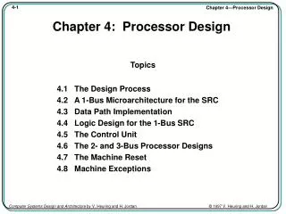
Chapter 4 Processor Technology and Architecture
Chapter 4 Processor Technology and Architecture. Chapter Goals. Describe CPU instruction and execution cycles. Explain how primitive CPU instructions are combined to form complex processing operations.

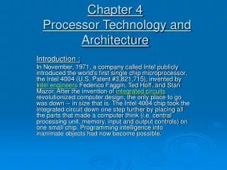
Chapter 4 Processor Technology and Architecture
E N D
Presentation Transcript
Chapter Goals • Describe CPU instruction and execution cycles. • Explain how primitive CPU instructions are combined to form complex processing operations. • Describe the key CPU design features, including instruction format, word size, and clock rate. • Describe the function of general-purpose and special-purpose registers. • Compare and contrast CISC and RISC CPUs. • Describe the principles and limitations of semiconductor-based microprocessors.
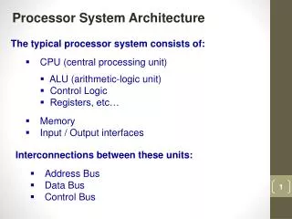
CPU Operation Central Processing Unit Components: • Control Unit • Arithmetic and Logic Unit • Registers
CPU Operation Control Unit – moves data and instructions between main memory and registers. Arithmetic and Logic Unit – performs all computation and comparison operations. Registers – storage locations that hold inputs and outputs for the ALU.
CPU Operation Main Actions performed by the CPU: • Fetch cycle (or instruction cycle) – data inputs are prepared for transportation into data groups. During the fetch cycle the control unit: • Fetch an instruction from primary storage • Increment a pointer to the location of the next instruction • Separates the instruction into components-the instruction code (or number) and the data inputs to the instruction • Stores each component in a separate register • Execution cycle – the transformation takes place and data output is stored. During the execution cycle the ALU: • Retrieves the instruction code from a register • Retrieves data inputs from registers • Passes data inputs through internal circuits to perform the addition, subtraction, or other data transformation • Stores the result in a register
CPU Operation Solid line: The flow between instruction and execution cycles Dashed line: Movement of Data & Instruction
Instructions and Instruction Sets • Parts of an instruction • Characteristics of an Instruction • Data movement instruction • Data transformation instructions • Sequence control instructions • Complex processing operations
Instructions and Instruction Sets Instruction – a command to the CPU to perform one of its primitive processing functions. It has 2 parts: Op Code – the unique binary number of the instruction. Operand – groups of bits that hold the input values for the instruction.
Instructions and Instruction Sets Instruction Set: collection of instructions that a CPU can process.
Instructions and Instruction Sets Characteristics of an Instruction Set: • Size of the instruction set • Size of the individual instructions, op codes, and operands • Supported data types • Number and complexity of processing operations implemented as individual instructions
Data Movement Move Instruction: • Copies data bits to storage locations • Transfers data from main memory into registers (load instruction) • Transfers data from registers to primary storage (store instruction)
Move Accesses to Storage & I/O Devices • An input or storage device writes to a specific memory location and the CPU retrieves the input by reading that memory location and copying its value into a register. • Data is output or stored by writing to a predefined memory address or range of addresses. The output or storage device continually monitors the content of its assigned memory addresses and reads newly written data for storage and output.
Data Transformation Primitive Data Transformation Instructions: • NOT • AND • OR • XOR • ADD • SHIFT
NOT Instruction The NOT instruction transforms the boolean value true into false and the value false into true. NOT 0 = 1 NOT 1 = 0
AND Instruction The AND instruction generates the result true if both of its data inputs are true. 0 AND 0 = 0 1 AND 0 = 0 0 AND 1 = 0 1 AND 1 = 1
Inclusive OR Instruction The Inclusive OR instruction generates the value true if either or both data inputs are true. 0 OR 0 = 0 1 OR 0 = 1 0 OR 1 = 1 1 OR 1 = 1
Exclusive OR Instruction The Exclusive OR Instruction (XOR) generates the value true if either, but not both, data inputs are true. 0 XOR 0 = 0 1 XOR 0 = 1 0 XOR 1 = 1 1 XOR 1 = 0
ADD Instruction The ADD instruction accepts two numeric inputs and produces their arithmetic sum. 0 + 0 = 0 1 + 0 = 1 0 + 1 = 1 1 + 1 = 10
SHIFT Instruction The Shift instruction moves bit strings to the left or the right.
SHIFT Instruction The Shift instruction moves bit strings to the left or the right. Original Byte Shifted two bits to the right Fig 4-5
Logical Shift Instruction The Logical Shift instruction is typically used to extract a single bit from a bit string.
Arithmetic Shift Instruction The Arithmetic Shift instruction performs multiplication or division. Multiplication – shifting one bit to the left, multiplies the value by 2. Division – shifting one bit to the right, divides the value by 2.
Sequence Control The Branch instruction causes the process to depart from sequential instruction order. Types of Branch instructions: • Unconditional Branch • Conditional Branch
Sequence Control The Unconditional Branch causes the processor to always depart from the normal sequence. The Conditional Branch occurs only if a specified condition is met.
Halt Instruction The Halt instruction suspends the normal flow of instruction execution in the current program.
Complex Processing Operations Complex processing operations can be performed by combining the simpler operations. Examples: A – B = A+(–B): i.e. –B is 2’s complement of B So calculate 2’s complement of B and add it to A. –B =Two’s complement of B = !B+1 [Ref to ch3 two’s complement] Example: T = 710-310= 0111+[!(0011)2+00012]= 0111+[11002+00012]=0111+[11012] = 10100= 0100 But !(0011) = XOR(0011,1111)=1100 So 2’s complement is XOR(0011,1111)+0001=1101 Then T = ADD( 0111, ADD(XOR(0011,1111),0001) ) 1100 1101 10100
If (Balance<100) Then Balance=Balance -5 End if Complex Operations, Example: $64=0100 0000 0110 0100 ! 0110 0100 -100 64-100 Table 4-2: Register contents after executing each instruction in Fig 4-8 when account balance in M1 is $64 Figure 4-8: A Simple Program Using Primitive CPU instructions
Instruction Format An instruction format is a template that specifies the number of operands and the position and length of the op code and operands. Figure 4-9: An instruction format with three register operands
Instruction Format Figure 4-10: An instruction format that uses segmented memory
Instruction Length Fixed instruction length – simplify the instruction-fetching processes implemented with the control unit. Variable instruction length – the amount by which the instruction pointer is incremented after the fetch is the length of the most recently fetched instruction.
Instruction Set Computing • Reduced Instruction Set Computing (RISC) - the absence of all, but not all, complex instructions in the instruction set. • Complex Instruction Set Computing (CISC) - uses instructions that do more work per instruction. As a result, programs require less memory, and complex operations executed more quickly.
Clock Rate Clock Rate – the frequency at which the system clock generates timing pulses. The rate are measured in Hertz (Hz) – one cycle per second. Cycle Time – The inverse of clock rate. In most CPUs, is the time required to fetch and execute the simplest instruction in the instruction set (e.g. NOT).
Clock Rate / Cycle Time • Each tick of clock begins a new clock cycle Clock Rate (Hz or # Cycle per second) Cycle Time = inverse of Clock Rate
Technology Focus - Benchmarks Benchmark: measure of CPU or computer system performance when carrying out one or more specific tasks Benchmark program: performs specific tasks that can be counted or measured Benchmark suites: combination of a variety of application programs Benchmarking organizations 40
CPU Registers Register Types: • General-purpose • Used by currently executing programs. • Hold intermediate results. • Hold data values. • Special-purpose: • Used by the CPU for a specific purpose. • Instruction register, • stores the instruction the control unit fetches from memory. • Instruction pointer, • stores the location of the next instruction to be fetched by the • Program status word. • stores data that describes the status of the CPU and currently executing program.
Word Size Word – unit of data that contains a fixed number of bytes or bits. The amount of data that a CPU processes at one time.
Enhancing Processor Performance • Memory Caching (Ch 5) • Pipelining • Branch Prediction and Speculative Execution • Multiprocessing Different forms of parallel processing
FIGURE 4.12 Overlapped instruction execution via pipelining Courtesy of Course Technology/Cengage Learning 44
Multiprocessing Duplicate circuitry for some or all processing stages within a single CPU Duplicate CPUs implemented as separate microprocessors sharing main memory and a single system bus Duplicate CPUs on a single microprocessor that also contains main memory caches and a special bus to interconnect the CPUs 45
The Physical CPU • Switches and Gates • Electrical Properties • Processor Fabrication
The Physical CPU Switches and Gates: the basic building blocks of computer processing circuits are electrical gates. Basic processing functions on binary digits are performed with the logical functions: (AND, OR, XOR, and NOT)
The Physical CPU NOT ! AND . OR + XOR + NAND
The Physical CPU More complex processing functions require more complicated arrangements of gates. A full-adder and half-adder can be formed using the basic gates.
Half-adder • A half-adder accepts two binary digits on its inputs and produces two binary digits on its outputs, a sum and a carry bit. Truth table for Half-adder